 Copyright Infinitybox, LLC 2021. All Rights Reserved.
 Fuel Pump Trigger
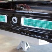
Let’s talk about fuel pump triggers. In a previous post, we talked about wiring the fuel pump to the POWERCELL output. In this post, we’re going to talk about how to connect the MASTERCELL input to the fuel pump trigger. We’re getting towards the end of our customer’s install of our 20-Circuit Kit into their 1967 Mustang. In previous posts, we’ve shown how to mount the MASTERCELL, POWERCELL and primary fuses. We’ve shown how to run the primary power cables and the CAN cable that connects the cells together. We’ve gone step-by-step through the process of connecting the POWERCELL outputs to the lights, fans, ECU, starter solenoid, fuel pump and other switched loads. We’ve shown how to connect your MASTERCELL inputs to the different switches in the car.
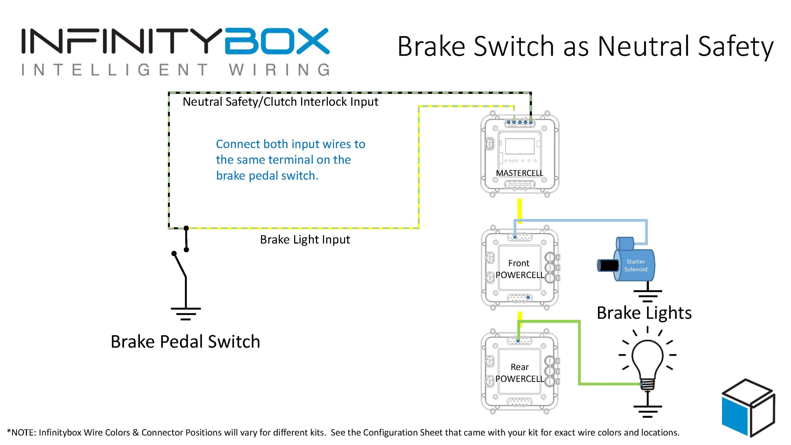
It’s time to wire the fuel pump trigger. Remember how the Infinitybox system works, your loads (lights, fans, pumps, ECU, starter solenoid and other switched functions) get their switched power from the POWERCELLs. You place the POWERCELLs locally in the car where you need them. You connect your switches to the MASTERCELL, which is usually under the dash. The MASTERCELL connects to the POWERCELLs through a thin data cable. When you turn on a switch, the MASTERCELL sends a command to one of the POWERCELLs to turn on an output.
In the case of the fuel pump, there is a dedicated output on the rear POWERCELL. In the case of this 1967 Mustang Kit, this is the tan wire on the POWERCELL A output harness. That is output 10. The input wire to the MASTERCELL is number 19. This is the tan wire with the yellow tracer wire on the MASTERCELL B input harness. Check your configuration sheet for the specifics on the POWERCELL output wire and the MASTERCELL input wire.
When you ground the MASTERCELL input wire for the fuel pump, the MASTERCELL sends a command to the rear POWERCELL to turn on 12-volts on output 10. This provides the switched battery power to the fuel pump. When you disconnect the MASTERCELL input wire from ground, the POWERCELL turns off the output for the fuel pump.
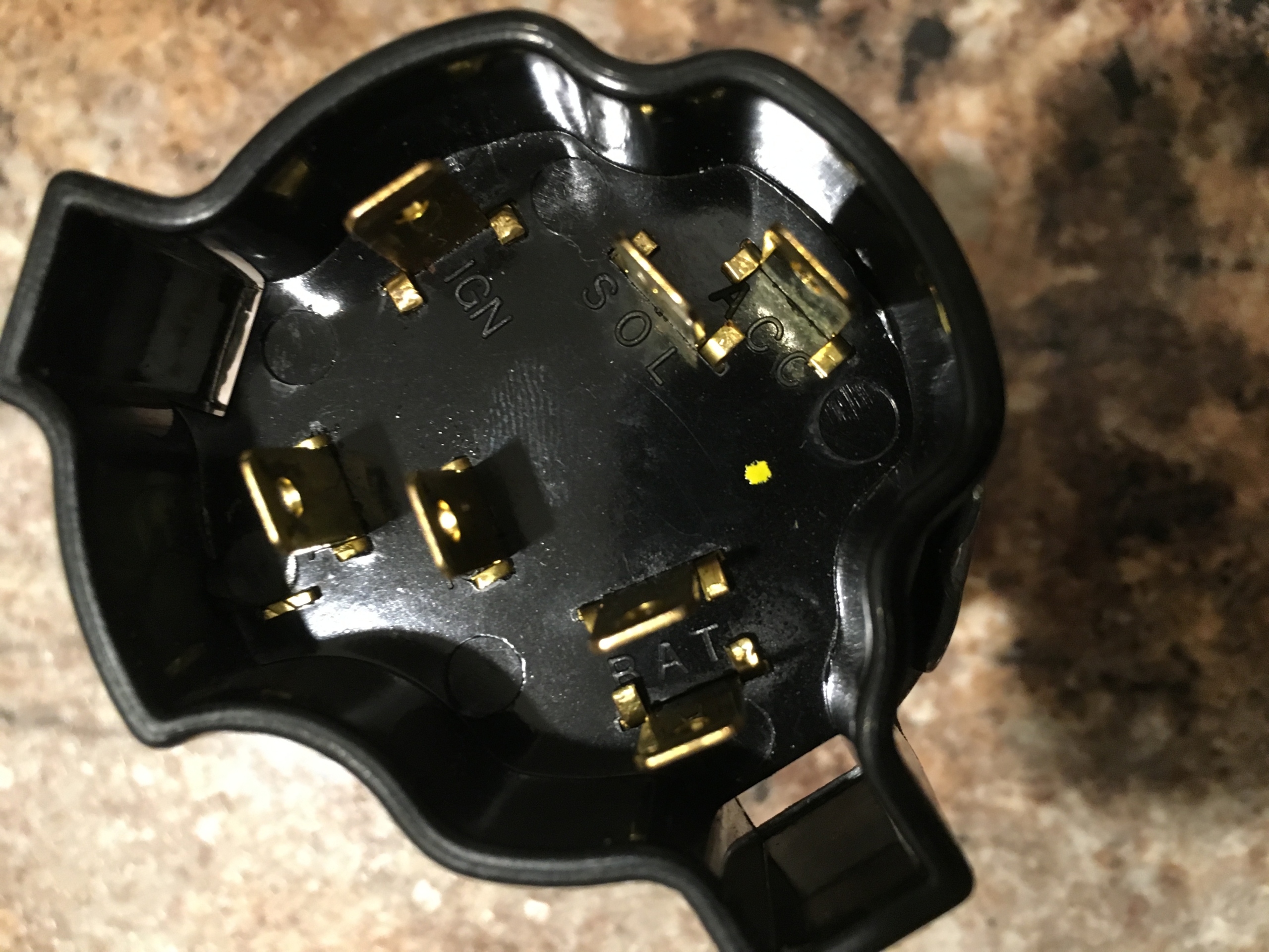
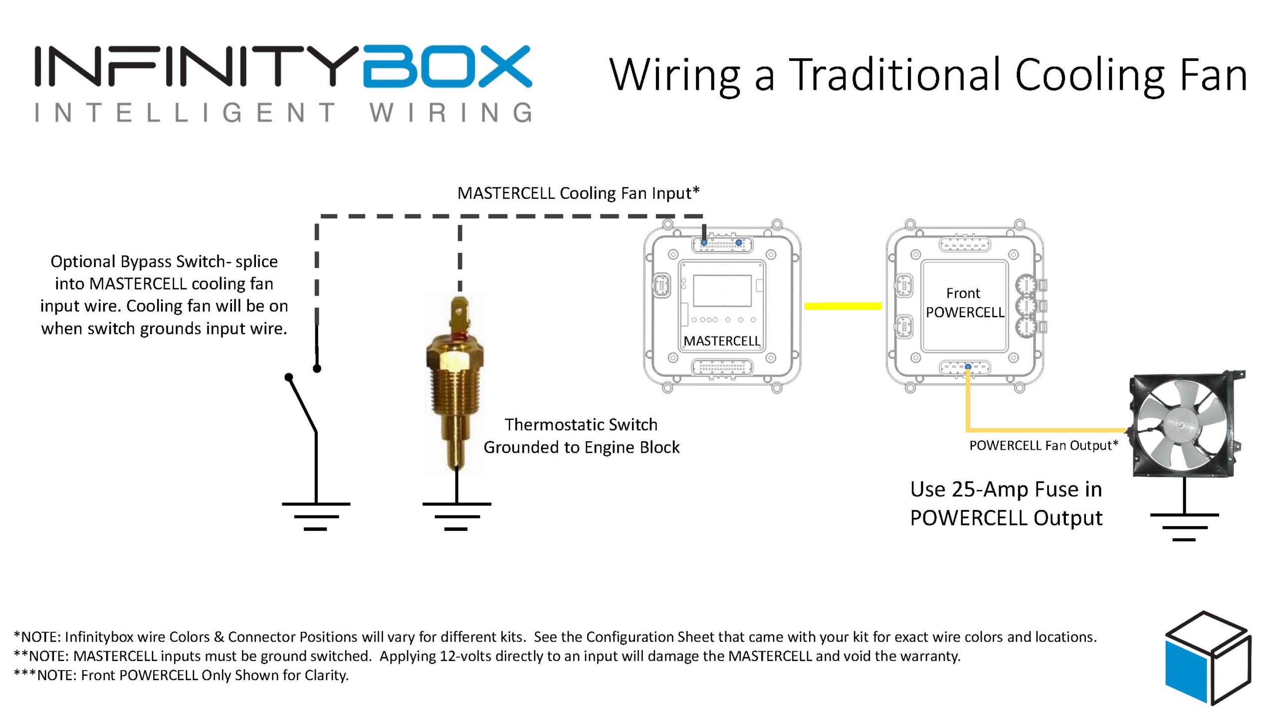
Our customers have many different ways that they want to control their fuel pump. The easiest is to trigger it with the ignition switch. To do this, simply connect the fuel pump input wire to the ignition terminal on the key switch. This wire is would be wired to the same terminal as the MASTERCELL input for ignition. When the key is in the run position, the inputs for both the ignition and fuel pump would be connected to ground. The MASTERCELL would tell the front POWERCELL to turn on the ignition output and tell the rear POWERCELL to turn on the fuel pump output.
Another way to do this is to have a separate switch for the fuel pump. Most race cars have this. A lot of guys will wire their cars this way because it is easier to work on the car plus it gets you an extra level of security. Unless you know to flip the fuel pump switch, the car won’t start. You’d wire a separate fuel pump switch no differently than any other switch to the MASTERCELL. The MASTERCELL input wire would connect to a normally open terminal on the switch. The other side of the switch would connect to ground. Turning on the switch connects the MASTERCELL input to ground, which turns on the fuel pump output on the rear POWERCELL.
Another option for controlling your fuel pump is to connect the MASTERCELL input to your ECU. Most engine management and EFI systems have an output that triggers the fuel pump. You can connect this wire from the EFI system to the MASTERCELL to have the ECU tell the Infinitybox system when the pump should be on or off.
There is an important warning that you must watch here. Remember that the MASTERCELL inputs are designed to be connected to ground. Applying battery voltage to the inputs may damage them and void the warranty. Carefully read the manual that came with your EFI system to understand how their fuel pump trigger is set up. They will usually be identified as either a positive or negative trigger.
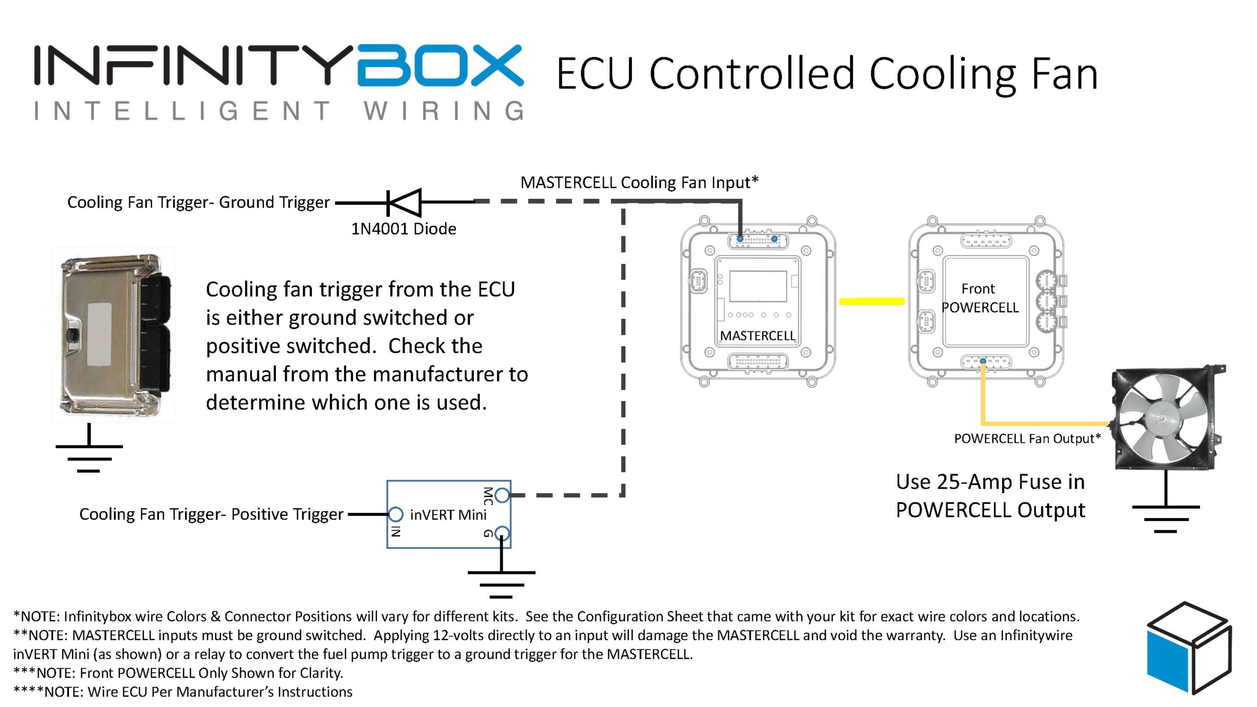
If the fuel pump trigger is negative, you can connect that to the MASTERCELL input wire. We strongly recommend soldering a 1N4001 diode in between the MASTERCELL input wire and the EFI system trigger wire for the fuel pump. This isolates the MASTERCELL from the EFI system. Diodes are directional parts so you must wire them with the cathode side facing towards the ECU. That is the side of the diode that has the stripe on it. This picture shows an example of the FAST EZ-EFI system and how to wire the diode into the fuel pump trigger.

Picture of wiring diagram showing how to wire the FAST EZ-EFI fuel injection system with the Infinitybox system.
If your EFI system has a positive trigger for the fuel pump, you must convert this positive signal to a negative signal. The easiest way to do this is to use one of our inVERT Mini’s. This is a small converter that is loomed in the harness. It so small, you hardly notice that it is there. This link will take you to more information on the inVERT Mini. Another option to flip the fuel pump trigger to a ground trigger is to use a relay. This link will take you to a diagram showing how to use a typical automotive relay to flip a positive trigger to a negative trigger.
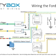
In the case of our customer’s 1967 Mustang, they are using the Ford Coyote crate engine. That has a positive fuel pump trigger. They chose to use an inVERT Mini to flip the positive signal from the ECU to a ground trigger to the MASTERCELL. This picture shows the wiring diagram for the Coyote ECU and how the inVERT Mini is wired into the harness.
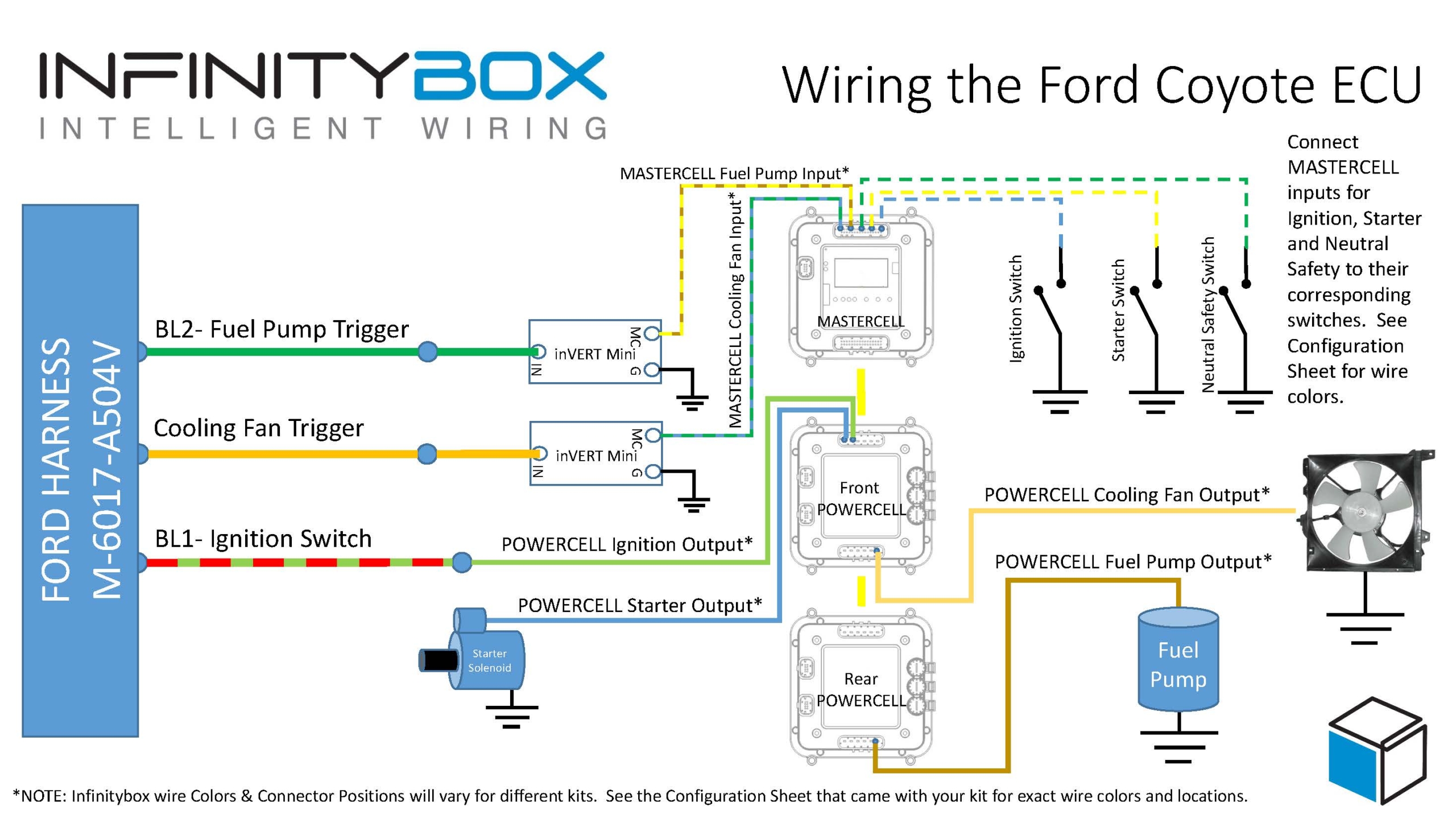
Image of wiring diagram showing how to wire the Ford Coyote ECU with the Infinitybox 20-Circuit Kit
You can download a PDF of this Coyote wiring diagram by clicking this link.

 Copyright Infinitybox, LLC 2021. All Rights Reserved.

 Copyright Infinitybox, LLC 2021. All Rights Reserved.


 Copyright Infinitybox, LLC 2021. All Rights Reserved.