 Copyright 2022 Infinitybox, LLC. All Rights Reserved.
 Soldering Components In-Line
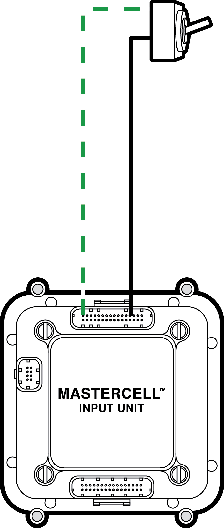
Okay… we do our best to not take things for granted. In all of our blog posts, we always try to give you as much fundamental information on the material that we are presenting. Every once in a while, we get called out by our customers for not explaining something thoroughly. This post is intended to fix this. In a lot of our blog posts and wiring diagrams, we show components installed in-line with a MASTERCELL input or a connection to ground.
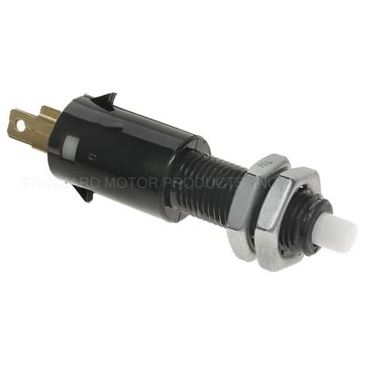
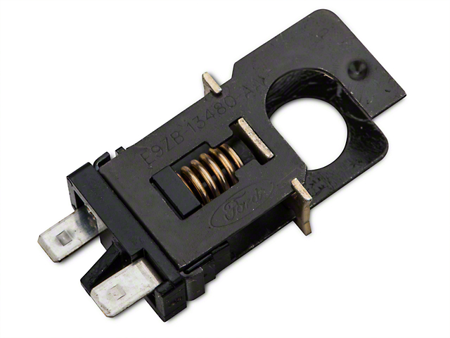
In our last blog post, we showed wiring a 10K pull up resistor on a brake-pedal switch. You can see that blog post here. In other blog posts, we’ve shown wiring diodes in-line between a trigger on an ECU and a MASTERCELL input. You can click here to see a recent example blog post. Someone just asked us an obvious question on our last blog post. “How do I install the diode or the resistor in the wire”. We’ll show you how. This isn’t the only way to do this but it is our recommended way to do this.
There are three important factors to consider when installing an in-line component in a wire. First, you need to have good electrical connection. Second, you need to protect it mechanically. Lastly, you need to protect the joint from the environment.
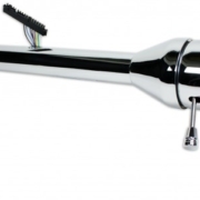
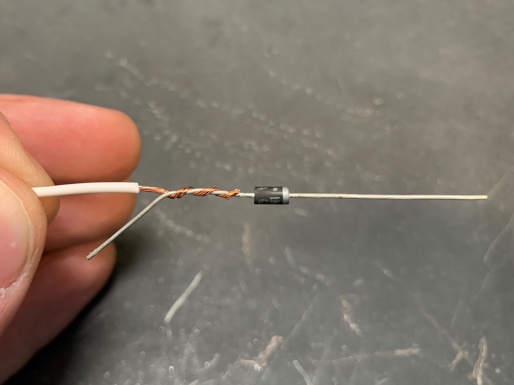
These steps will show you how to solder an axial, leaded component in-line with a wire. A leaded part has metal terminals coming off its ends. An axial part has the leads running along the axis of the component. This picture shows you a good example of an axial, leaded diode.
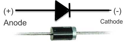
Example of a simple diode
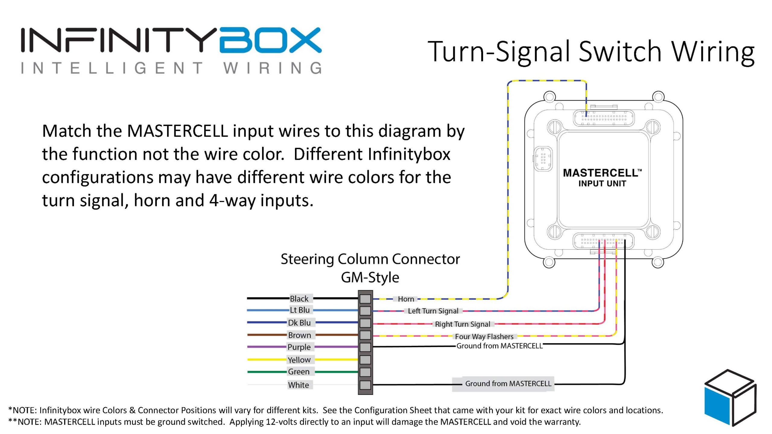
Speaking of diodes, remember that they have a direction to them. Check our wiring diagram for proper orientation of the diodes. Resistors do not have a direction so you can install them either way in your wiring harness.
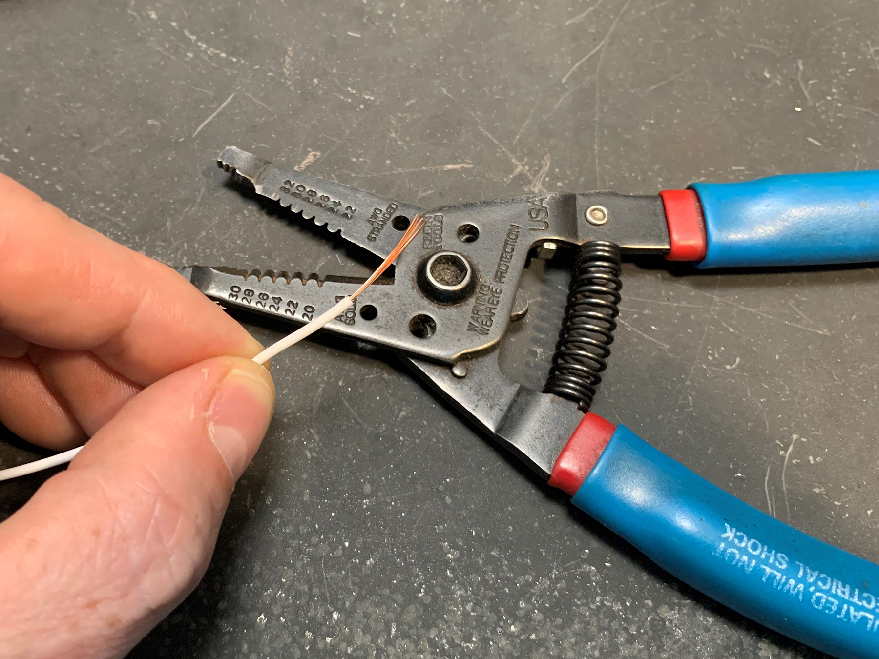
The first step is to strip back the insulation on the wire you’re connecting to your component.
Next, you want to twist the strands of the copper wire together. This will make the next steps easier by keeping the strands together.
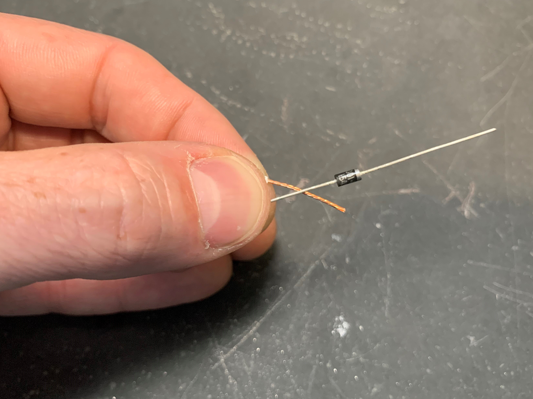
Next, twist the strands of the wire with the lead coming from your component. We recommend leaving some length of the lead at the end as shown in this picture.
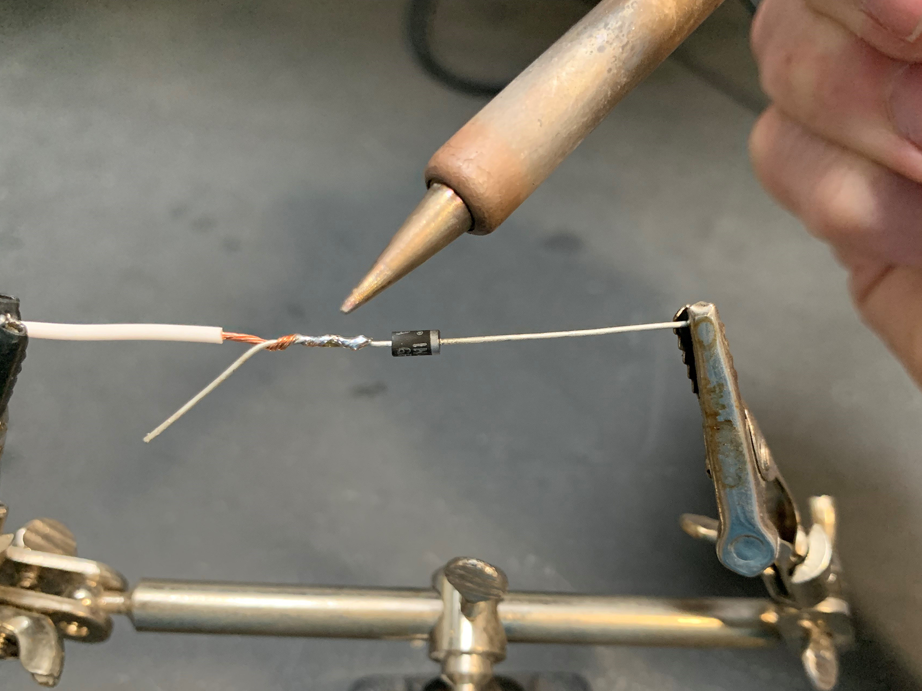
The next step is to make a good electrical connection between your wire and the lead on your component. This needs to be soldered. A good soldering iron and electrical solder will make this job easy. You want to make sure that you are heating the joint thoroughly and that the solder is flowing between the copper wire and the lead on your component. When you’re finished, the joint should be shiny. If your joint looks grey or dull, you need to apply more heat and solder. We also recommend keeping the solder on the joint between the copper wire and the lead on the component. You do not want the solder to wick up the copper wire under the insulation. This will make the joint inflexible and it could fail over time.
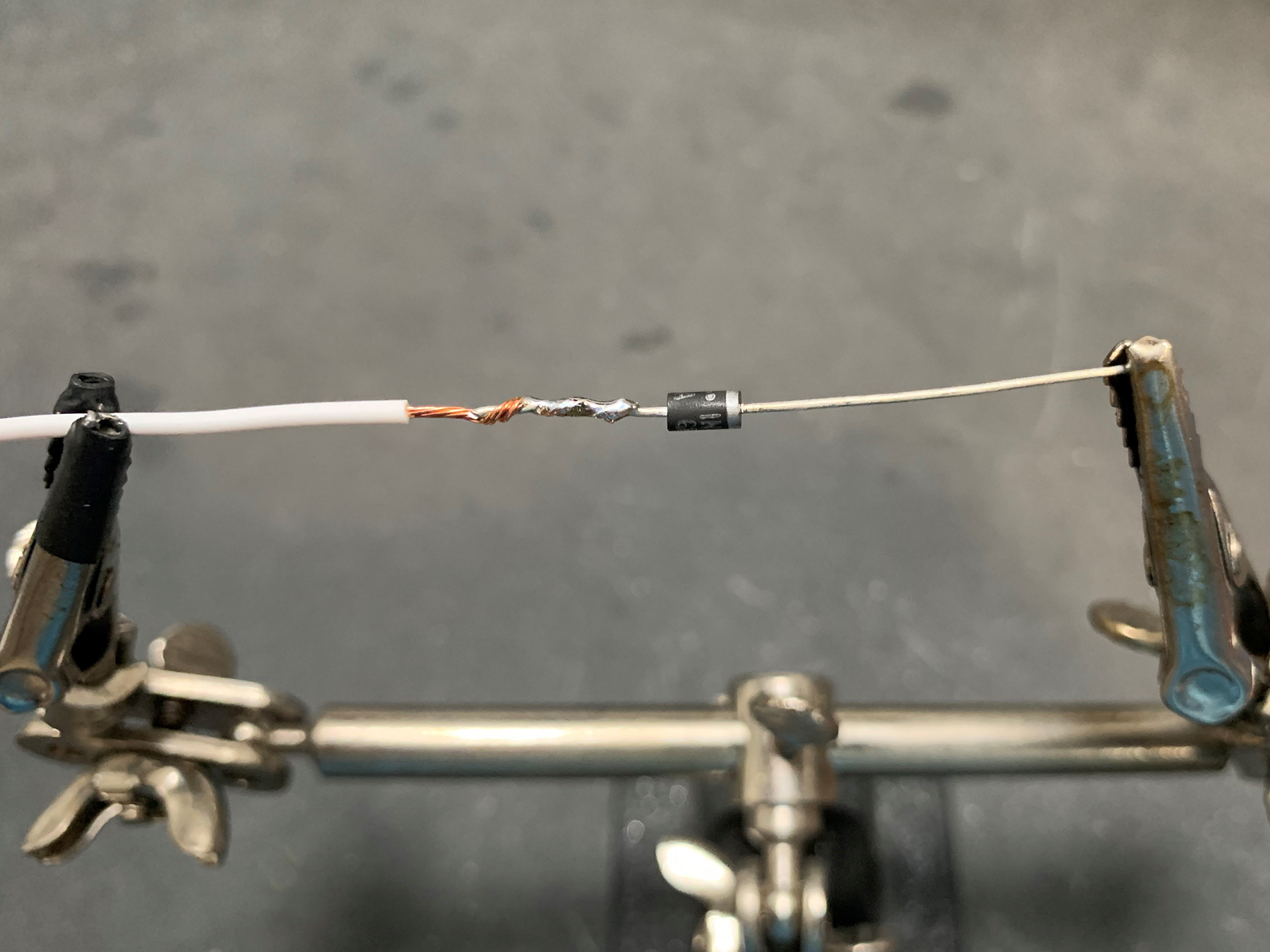
Once you have the joint soldered, clip off the extra length of lead on the component.
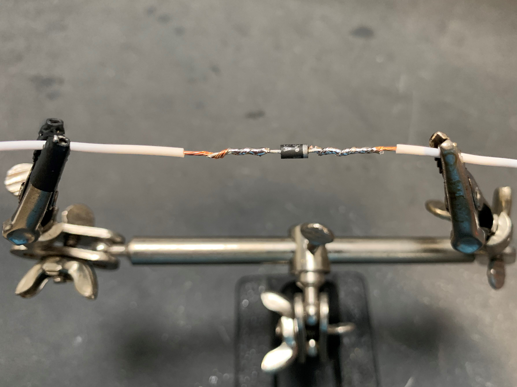
Repeat this process for the other side of your component.
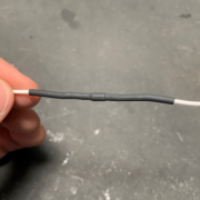
Now you have a good electrical connection between your wires and your component. The next step is to protect the component mechanically and from the environment. To do this, we recommend a good quality heat shrink tubing. Heat shrink tubing does what its name suggests. It shrinks around a joint when you heat it. Cut a length of heat shrink tubing that is slightly larger in diameter than the component that you soldered in line. You want the length of this tubing to extend past the exposed area of your joint by about 1/2″ on both sides.
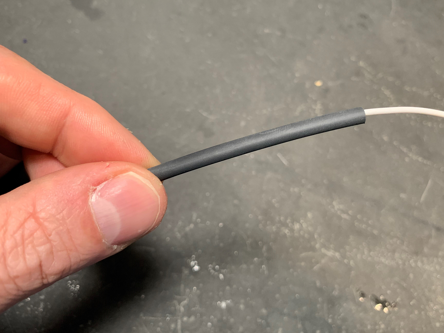
Use a hot air gun to heat the tubing and shrink it over the component and the joints. We know that a lot of guys like to use lighters or torches to do this but we really recommend a hot air gun for better control and safety.
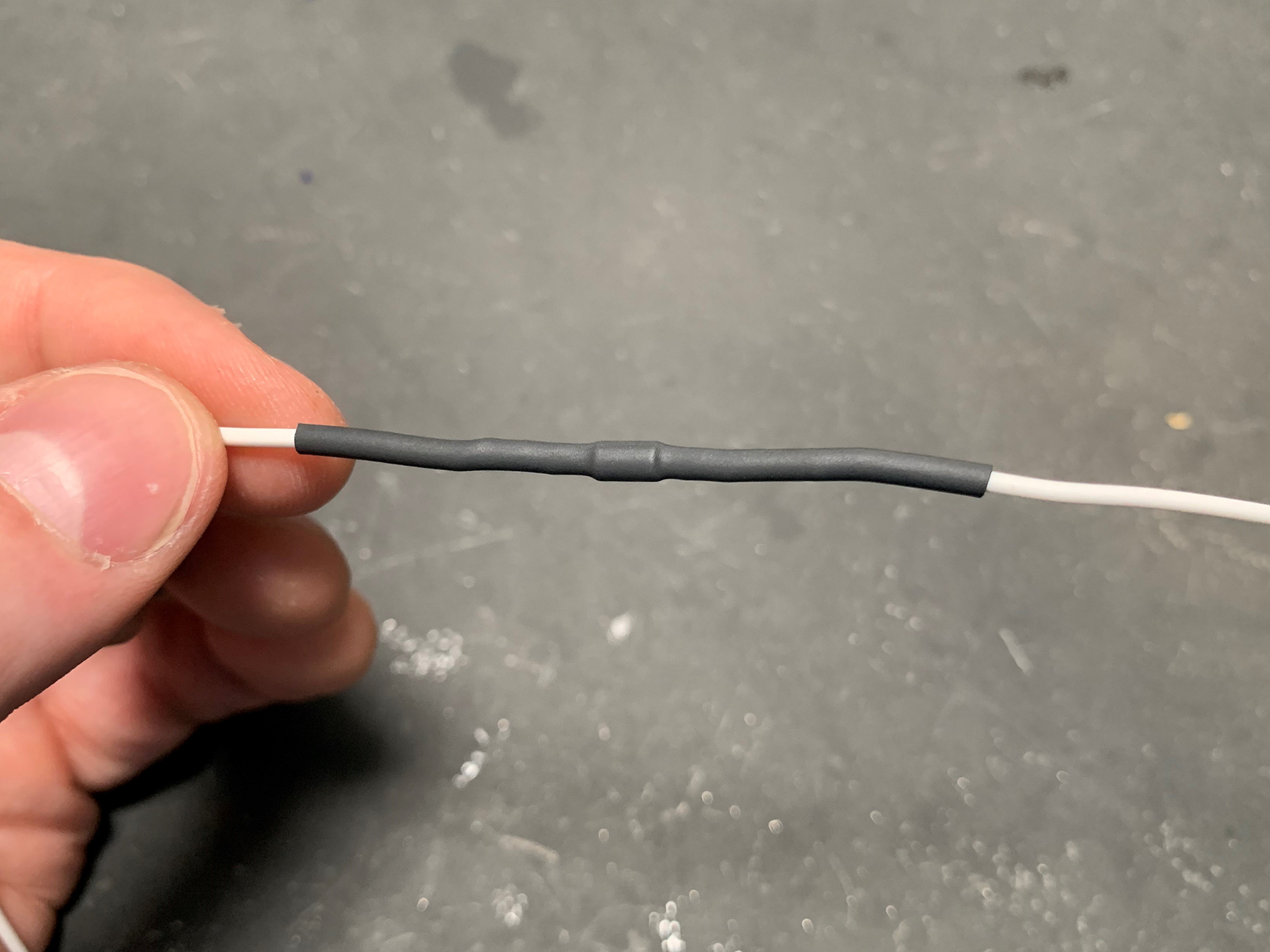
The heat shrink tubing is going to do two important things. First, it is going to mechanically strain relieve your joints. This will keep the joints from failing due to vibration of mechanical stress. We recommend that you zip tie these components in the harness to minimize any bending or movement as an added precaution. Secondly, the heat shrink tubing is going to protect the joints from exposure to moisture, dirt and other chemicals in your car.
Soldering in-line components in your harness is a simple thing to do. If you have any additional questions about this, please click on this link to contact our technical support team.
 Copyright Infinitybox, LLC 2021. All Rights Reserved.
 Copyright Infinitybox, LLC 2021. All Rights Reserved.
 Copyright Infinitybox, LLC 2021. All Rights Reserved.
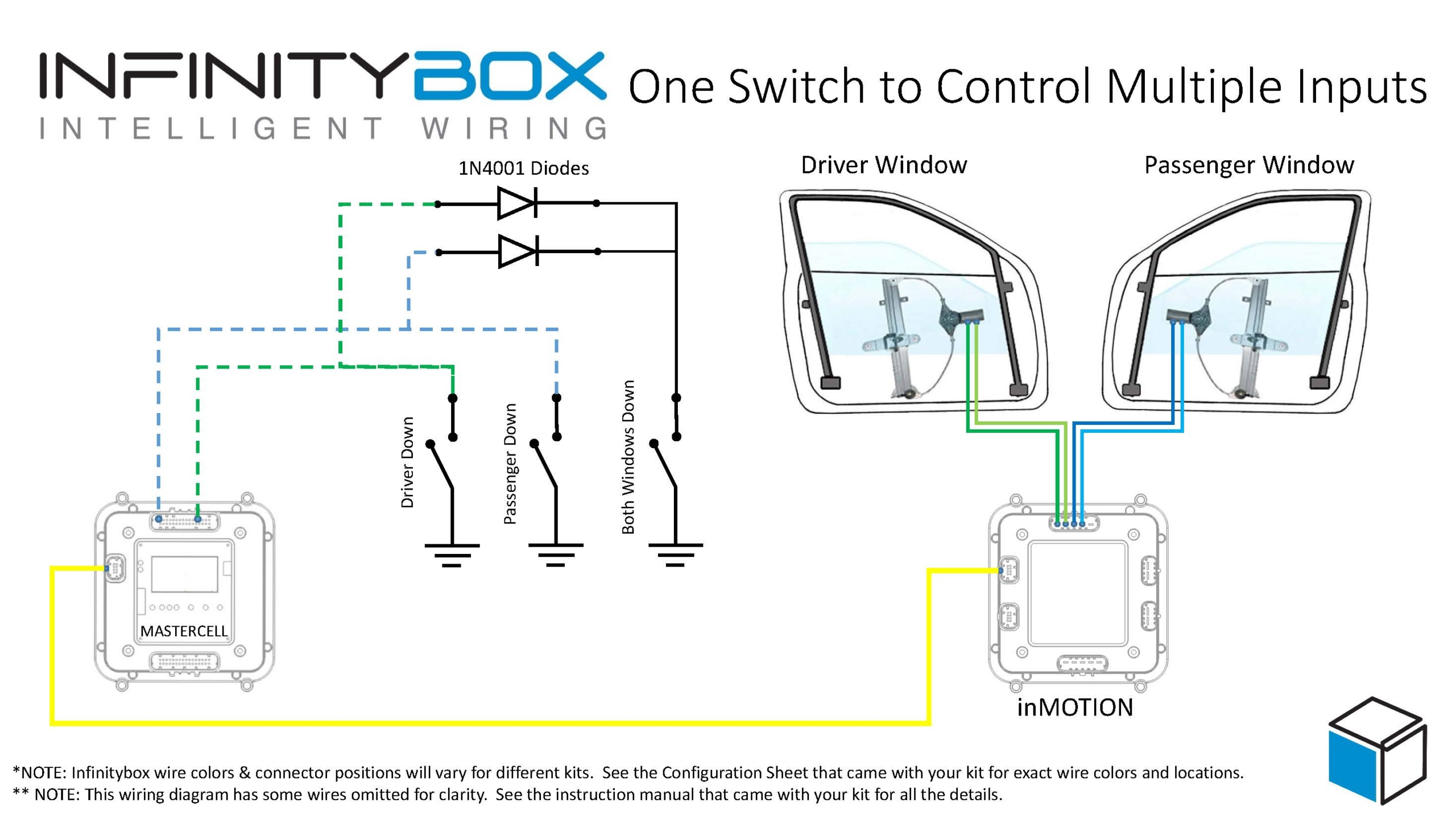


 Copyright Infinitybox, LLC 2021. All Rights Reserved.