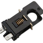
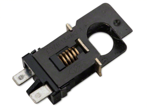
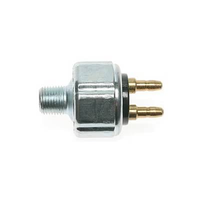
Picture of a lost-travel brake switch. Commonly found in Ford Mustangs.

Brake Switch

In previous posts, we talked about how to wire the brake lights to the rear POWERCELL in our customer’s 1967 Mustang.  We’re going to talk about wiring the brake switch in this post.  This is a very easy MASTERCELL switch input to wire.  There are lots of different brake pedal switches out there.  Here are a few examples from the Summit Racing website.
 

Hydraulic pressure brake switch
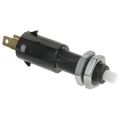
Hydraulic pressure brake switch

MOPAR-style brake switch
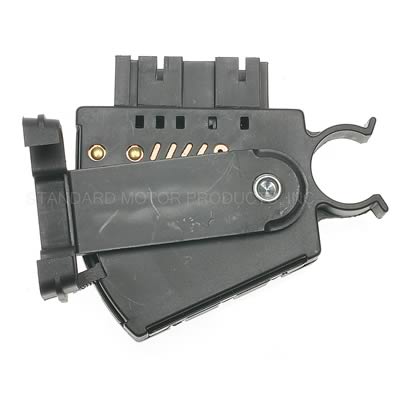
MOPAR-style brake switch

Automotive brake pedal switch

Automotive brake pedal switch

Picture of a lost-travel brake switch. Commonly found in Ford Mustangs.

Picture of a lost-travel brake switch. Commonly found in Ford Mustangs.

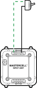
This last brake switch is what our customer is using in the 1967 Mustang.  All of these switches have 2 terminals on them.  One will connect to the MASTERCELL input wire.  The other will connect to ground.  When the pedal is pressed, there is continuity between the MASTERCELL input wire and ground.  Refer back to this illustration again.

Simple diagram showing how to wire a switch to the Infinitybox MASTERCELL

Simple diagram showing how to wire a switch to the Infinitybox MASTERCELL

The brake pedal switch simply connects between the MASTERCELL input and ground.

Start by checking the configuration sheet that came with your kit.  This link will take you to an earlier post in this series about the importance of your configuration sheet.  This car is wired with separate brake light and turn signal outputs on the rear POWERCELL so we’re going to use the MASTERCELL input for Brake Lights with Multi-Filament Bulbs.  This post will get you more information on the different turn-signal and brake light options.

We checked our configuration sheet.  The MASTERCELL input for the brake switch for the configuration that we want is the Yellow-Green wire.  This is input 15 on the MASTERCELL A connector.  Remember that the MASTERCELL input wire needs to connect to one side of the switch.  The other side of the switch needs to connect to ground.  In the case of the brake switch, there is no polarity.  You can connect the MASTERCELL input to either of the terminals on the switch.

In the case of the Mustang switch, you can purchase the mating connector and harness that plugs onto the back of the switch.  This has the two wires that connect to the MASTERCELL input and ground.  You can splice or solder these wires in any way as described in previous posts in this series.

For the ground connection, you have two options.  You can make the ground connection directly to the chassis at the brake pedal.  Make sure that this connection is made on the body, not on the brake pedal mechanism.  You will not get good continuity to ground through the pedal linkage.  Put a ring terminal on the ground wire to connect to the chassis.  Make sure that you have a metal-to-metal connection for this ground.  The junction should be free of dirt, grease, oil, rust, paint, powder coating or any other contaminant.

You also have the option to use any of the black wires in the MASTERCELL harness as your ground connection.  There are 8 black, ground wires in the MASTERCELL A harness.  All 8 of these wires are electrically the same.  You can use any of them to be the ground connection for your brake switch.

Here’s how your brake light circuit will work when it is connected.  When you step on the brake pedal, the contacts in the brake switch close.  This connection takes the MASTERCELL brake input and connects it to ground.  The MASTERCELL detects that the input has been grounded and sends a command to the POWERCELL in the rear of the car.  The POWERCELL receives this signal and turns on the output for the brake lights.  When you take your foot off of the brake pedal, the contacts in the brake switch open.  This disconnects the MASTERCELL input from ground.  The MASTERCELL sees this input turn off and sends a command to the rear POWERCELL.  The rear POWERCELL gets this command and turns off the brake lights.  It seems complicated, but it isn’t.  All of this is automatically managed from within the Infinitybox system.

If you have questions about connecting your brake switch, you can click on this link to contact a member of our team.  Keep watching our blog for more updates on wiring switches in our customer’s 1967 Mustang.

Wiring Switches

It is time to get into the next phase of wiring this 1967 Mustang with our Infinitybox 20-Circuit Kit.  We got the cells mounted, mounted the Mega fuses, wired primary power from the battery, ran the CAN cable and wired the outputs to the POWERCELLs.  It’s time to start wiring switches to the MASTERCELL inputs.

Here’s a quick refresher.  Our Infinitybox system is different than any other wiring harness on the market.  Instead of having one central box full of fuses and relays with wire running everywhere in the car, our system is broken into smaller modules.  Our POWERCELLs are mounted in the front and rear of the car.  They contain the fuses and relays to turn your accessories on and off.  The MASTERCELL connects to the switches.  You mount the MASTERCELL under the dash and wire your switches to it.  The MASTERCELL sends commands to the remote POWERCELLs through our CAN cable to control your lights, fans, fuel pump, horns, ignition, starter solenoids and other switched functions.  This is going to be the first in a series of posts talking about wiring switches.

Remember that all of your switches will connect to your MASTERCELL.  This includes switches for your ignition, starter, turn signals, brake lights, headlights, parking lights, high-beams, cooling fans, fuel pump, horn and anything else that you need to turn on and off in the car.  There is no direct connection between your switch and the output.  The MASTERCELL watches all of the switches.  When it sees a switch turn on or off, it sends a packet of data through the CAN cable to the remote cells in the car.  These cells could be POWERCELLs or inMOTION cells.  The remote output cells are what control the current flowing to your switched loads.

The MASTERCELL needs a simple trigger signal from each switch.  These triggers are a connection to ground.  Each trigger takes a very small amount of current to send the signal to the MASTERCELL, less than 0.001-Amp.  This picture shows a very simple switch wired to a MASTERCELL input.

Simple diagram showing how to wire a switch to the Infinitybox MASTERCELL

Simple diagram showing how to wire a switch to the Infinitybox MASTERCELL

In this diagram, the MASTERCELL input wire connects to one terminal of the switch.  The other side of the terminal needs to connect to ground.  When the switch is on (closed) there is a path through the switch to ground.  This is what triggers the input on the MASTERCELL.  This picture shows using one of the ground wires that is included in the MASTERCELL input harness.

There are lots of advantages to using this kind of input when you are wiring a car.  Ground switching the inputs means that you do not need to run a positive wire to each switch.  The MASTERCELL input harnesses have ground wires that you can use for your switches.  You can also use the chassis in the car as the ground reference for your switches.  You just need a good metal-to-metal connection to ground.

Another advantage is that it takes a very small amount of current to turn on an input.  This means that we can use a much smaller gauge of wire in the input harness.  We use 22-AWG TXL wire on the inputs.  This will reduce the bulk of harness behind your dash.  It also means that there is no high-current behind your dash.  All of the high-current control is at the POWERCELL.  It is always the small signal current through the MASTERCELL input wire regardless of what is being switched at the POWERCELL.  This means that you can use practically any switch to turn things on and off in your car.  You can use the original switches that came with the car.  You can use any aftermarket switch.  There is very little current flowing through the switch.

Just a quick warning:  The MASTERCELL inputs are designed to be switched to ground.  You must not wire your switches so that battery voltage can be applied to a MASTERCELL input.  Doing this may damage the circuitry inside the MASTERCELL and this will void the warranty.  Contact us with questions if you are uncertain about how to properly connect something to a MASTERCELL input.

Remember that your configuration sheet is your road map to wiring your car with our Infinitybox system.  Your configuration sheet will identify the wires by color for each of the switches in your car.  You can click on this post to get a refresher on your configuration sheet.

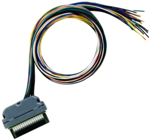
Every kit comes with a MASTERCELL A input harness.  This picture shows this harness.

MASTERCELL A Input Harness

MASTERCELL A Input Harness

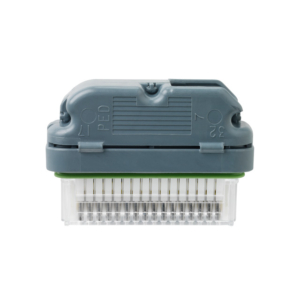
All of your switches will connect to the wires on this harness.  The B connector socket at the bottom of the MASTERCELL must have the input dummy plug installed to keep the cell sealed.  This picture shows the MASTERCELL input dummy plug.

Sealing plug for MASTERCELL B Port

Sealing plug for MASTERCELL B Port

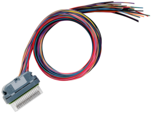
If you have a third POWERCELL as part of your system or if you have added inMOTION to your kit, you will get the MASTERCELL B harness.  This picture shows this harness.

MASTERCELL B Input Harness

MASTERCELL B Input Harness

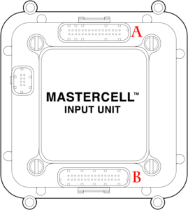
Your configuration sheet will show which harnesses have the inputs for your different switches.  This picture shows which is the A & B input connector socket on your MASTERCELL.

Illustration of Infinitybox MASTERCELL labeling output connectors

Illustration of Infinitybox MASTERCELL labeling output connectors

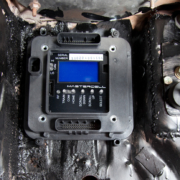
In the case of this 1967 Mustang project, the MASTERCELL is mounted under the dash, to the left of the pedals.  The input wires will run from the MASTERCELL to all of the switches.  This is a great location for this because all of the wire runs will be short.

We will be going through wiring switches in much more detail over upcoming blog posts.  Please keep watching our blog for updates.  You can click on this link to contact a member of our team with any questions.


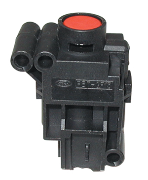
Picture of a fuel pump inertia switch

Inertia Switch

We just posted details on how to wire the fuel pump to our Infinitybox POWERCELL.  That was a very simple part of the wiring process in this 1967 Mustang.  We received a follow up question to this post about wiring a fuel inertia switch.  We’ll give details in this post.

A lot of manufacturers, Ford especially, use an inertia switch to interrupt the power going to the electric fuel pump in case of an accident.  These switches use an internal magnet and a ball bearing to close the circuit providing power to the fuel pump.  If there is a large impact to the car from a collision, the force of the impact knocks the ball out of its location.  This opens a set of contacts in the switch, which interrupts power going to the fuel pump.  These switches can be sensitive.  They may shut down the fuel pump if you get a flat tire or if you hit a large pot hole.  A lot of us here remember the prank of pounding on the driver’s rear fender in a mid-1990’s Thunderbird or Mustang to kill the fuel pump and leave a guy stranded.

Picture of a fuel pump inertia switch

Picture of a fuel pump inertia switch

If there was an accident, this switch opens and cuts off power to the fuel pump.  There is a reset button on the top of the switch.  If the red plunger is up, that means that the switch tripped.  If you press down on the plunger, it will reset the switch, letting the electric fuel pump operate again.

In some cars, these switches are in the rear near the fuel pump.  In other cars, they are up front behind the dash.  Wiring an inertia switch to your fuel pump powered by our 20-Circuit Kit is really easy.

You can purchase these switches from any on-line source.  This link will take to you the popular Ford switch sold on Amazon.  You can find the switches but you can’t always find any data or specifications on them.

Switches are only designed to carry a maximum amount of current.  You always have to consider that when you choose a switch.  That is true when you pick your inertia switch.  These switches were designed to interrupt the feed going directly to the fuel pump.  This means that the switch was designed to carry the current for that pump.  In the case of this 1967 Mustang, we are installing a higher-performance pump that draws much more current that the original OEM pump.

To be safe, use the inertia switch to interrupt the MASTERCELL input wire for the fuel pump.  Each of our inputs only require a very small amount of current to operate.  The contacts in the inertia switch can easily handle the small amount of current from the MASTERCELL.

Under normal operation, the MASTERCELL input will be connected to a switch that turns on the input for the fuel pump.  This could be a signal coming from an ECU, it can be from a separate fuel pump switch or it can be tied to the ignition switch.  The inertia switch would be wired in series.  If there were to be an accident, the input from the MASTERCELL would be interrupted by the open contacts in the inertia switch.  This would cause the MASTERCELL to send the command to the POWERCELL to turn off the fuel pump output.  Wiring the switch in with the MASTERCELL input ensures that you will never overload the contacts on the inertia switch.

Click this link to contact our team with questions or comments on this post.


Fuel Pump

Now it is time to wire the fuel pump to the POWERCELL in our 1967 Mustang project.  This is the last major output that needs to be wired in.  In our next series of posts, we will be talking about wiring the switches to the MASTERCELL.

There are lots of different kinds of electric fuel pumps for cars and trucks.  Primarily, they fall into two categories: in-tank and in-line.  These are pretty self-explanatory.  In-tank fuel pumps are mounted in the fuel tank.  In-line fuel pumps are installed somewhere in the fuel line running between the tank and the engine.  Our customer is using an Aeromotive 325 Stealth In-Tank Pump for this project.

Aeromotive Stealth Fuel Pump

Aeromotive Stealth Fuel Pump

Just like everything else in your car, thoroughly read and understand the manual that came with your fuel pump before you start this part of the install.  Remember that you are playing with Gasoline.

Wiring for the fuel pump is pretty simple.  The fuel pump needs battery power and ground.  The battery power is going to come from a POWERCELL output.  The ground connection is going to be made locally to the chassis.

This Aeromotive pump has two wires: red and black.  Black is ground and that is going to connect to the chassis.  Remember how important good ground connections are.  Make sure that you have a reliable metal-to-metal connection between your ground wire and the chassis.

The red wire is power.  This is going to connect to a POWERCELL output.  In most of our configurations, this power comes from output 10 on the rear POWERCELL.  This is the tan wire on the A connector.  The advantage of using our system to power the fuel pump is that the pump gets connected to the local POWERCELL.  The fuse and relay for that pump are built into the POWERCELL.  If you have a POWERCELL mounted in the rear of the car, the power wire going to the pump is very short.

We need to make a few comments about current draw.  Take a good look at the manual or specifications for your fuel pump.  You have 25-amps of steady-state current draw to work with on each POWERCELL output.  Aeromotive publishes great graphs in their manuals that show current draw and fuel flow versus pressure.  At the highest flow rate and highest pressure, this pump draws about 16-amps.  This is well below the 25-amp capacity of a single POWERCELL output.

In some cases, you need to provide power to the fuel level sender in the tank.  If yours needs to be powered, you can splice off the fuel pump output on the POWERCELL.  It is a good time to wire sender power if needed while you’re wiring power to the pump.

That’s it for wiring the fuel pump output.  We’ll talk about wiring the fuel pump trigger to the MASTERCELL in upcoming blog posts.  Click on this link to contact us with questions or comments.

Holley Terminator EFI

Our Infinitybox system can power any ignition and fuel injection system out there.  We recently received a request for a wiring diagram for the Holley Terminator EFI system.  We’ve blogged before about the Dominator and given detailed instructions on how to wire that system with our 20-Circuit Kit.  You can see that here.  This post will cover how to connect to the Holley Terminator EFI system with our 20-Circuit Kit.

Holley ECU

Holley ECU

Holley Terminator EFI System

This link will take you to more information on the Holley Terminator EFI system.  

Our Infinitybox 20-Circuit Kit is going to provide the ignition power to the Holley ECU.  It is also going to take the fuel pump trigger signal from their ECU and the cooling fan trigger.  These two triggers will go to the MASTERCELL which will send signals to the POWERCELL in the front of the car for the cooling fan and the POWERCELL in rear of the car for the fuel pump.  This eliminates the need to add external relays because they are switched from inside the POWERCELLs.  This also eliminates the need to run high-current wiring from the Holley Terminator EFI system to the front and back of the car.  Those signals are sent through our CAN cable.

Before we go any farther, it is very important that you completely read and fully understand the manual that came with your Holley Terminator EFI system.  There are many different parts of properly installing this system, the wiring is just one step.

Once you have read and understand their manual, you must make all of the constant power and ground connections necessary for their system to work.  There are multiple constant power feeds that must be wired directly to the battery and multiple ground connections.  You must also wire in all of the other connections including the coil, tach, O2 sensors, etc.  Their manual will cover these details.

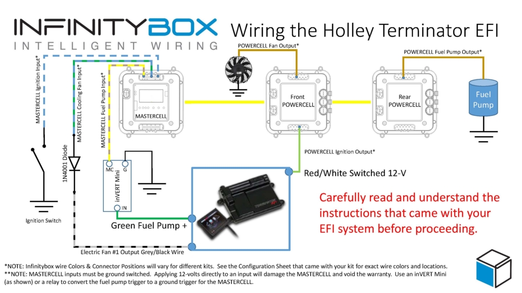
As an overview, here are the points where your 20-Circuit Kit will connect to the Holley Terminator EFI system.

  1. The ignition output on your POWERCELL will supply the key-on power to their system.
  2. Their system will trigger the fuel pump output on your rear POWERCELL from the MASTERCELL.
  3. Their system will trigger the cooling fan output on your front POWERCELL from the MASTERCELL.

This picture shows you the overview of the connections between your Infinitybox 20-Circuit Kit and the Holley Terminator EFI system.

Picture of Infinitybox wiring diagram showing how to wire the Holley Terminator with the 20-Circuit Kit.

Picture of Infinitybox wiring diagram showing how to wire the Holley Terminator with the 20-Circuit Kit.

You can download a PDF of this wiring diagram by clicking this link.

Let’s start with the key-on ignition power.  Check your configuration sheet and find the ignition output wire.  In most cases, this is the light-green wire on the front POWERCELL.  System configurations may vary so check the configuration sheet that came with your kit.  The POWERCELL ignition output wire is going to connect to the red wire with the white stripe in the Holley ECU harness.

Next, you need to connect the fuel pump trigger.  In the ECU harness, there is a green fuel pump wire.  This wire supplies 12-volts to drive a pump directly or to drive a relay coil.  To connect this to the MASTERCELL input, you must convert this 12-volt signal to a ground signal.  You can do this with one of our inVERT Mini’s.  Alternately, you can use a relay to flip this 12-volt signal to a ground signal for the MASTERCELL.  This link will take you to a diagram showing you how to use a relay if you don’t want to use an inVERT Mini.

Check the configuration sheet that came with your kit.  Find the MASTERCELL input wire for your fuel-pump.  In most cases this is input 19 which is the tan wire with the yellow stripe.  Check your configuration sheet to confirm this as different systems may have different wire colors.

Lastly, you need to wire the cooling fan trigger from the Holley Terminator EFI system to your MASTERCELL.  Check your configuration sheet for the color of this wire.  In most systems it is the blue wire with the yellow tracer.

There are additional outputs on the Holley harness.  The gray wire with the black stripe is the cooling fan trigger.  This is a ground-switched signal so you do not need to flip it to connect it to the MASTERCELL.  However, we do recommend using a diode to eliminate the chance of surges coming into the MASTERCELL inputs from the ECU.  A 1N4001 diode will do the job.  You can get these from any electronics source.  Please note that the orientation of the diode is very important.  The stripe on the diode should be on the ECU side of the connection, facing away from the MASTERCELL.

That’s it.  When you turn the key, the front POWERCELL is going to apply battery power to the ignition input on the Holley Terminator EFI system.  When the Terminator wants the fuel pump to turn on, it will send a signal to the MASTERCELL, which will control the fuel pump through the rear POWERCELL.  When the Terminator wants to turn the cooling fan on, it will send a signal to the MASTERCELL.  The MASTERCELL will tell the front POWERCELL to turn on the cooling fan.

If you have questions about wiring diagram or wiring anything else with our Infinitybox system, click on this link to contact a member of our team.

Horn

This is a really easy one.  It’s time to wire the horn on this 1967 Mustang project.  This post is going to talk about how to connect the horn output on the POWERCELL to the terminals on the horn.  It is pretty straight forward.

There is a dedicated output in your 10 or 20-Circuit Wiring Kit for the horn.  In the standard front-engine configuration, it is the orange wire on the front POWERCELL.  This is output 9 on the A connector.  Check the configuration sheet that came with your kit to verify this output.  When the MASTERCELL sees the horn input wire grounded, it sends a command to the front POWERCELL to turn the horn output on.  This applies battery voltage to the horn which makes it sound.  When the horn button is released, the MASTERCELL sees the input wire come off of ground.  The MASTERCELL sends a command to the POWERCELL to turn the horn output off.  Pretty simple.

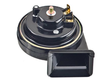
You are going to run the horn output from your front POWERCELL to the horn mounted in the car.  Most horns have two terminals on them.  One is the switched battery power.  The other is ground.  This picture shows an example horn.  This is the Wolo 315-2T.  The 2T stands for two terminal.

Example of a Wolo Horn

Example of a Wolo Horn

You can see the two terminals in the upper right of the picture.

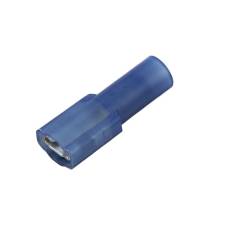
Most horn terminals are 1/4″ male Quick-Disconnect connectors.  You simply strip the POWERCELL output wire and crimp on a female Quick-Disconnect connector.  Some companies refer to these terminals as Push-On.  Others call them Fast-On terminals.  This picture shows an example of these terminals.

Fast-on female terminal

Fast-on female terminal

You can source these terminals from companies like Del City or Waytek Wire.  Make sure that you are getting the right width of terminal.  You also have to make sure that the terminal is the correct size for the gauge of wire.  Our POWERCELL outputs use 14-AWG wire.  Terminals to mate with 14-16 Gauge wire are usually blue.  Pink or Red terminals are usually for 18-22 Gauge wire.  We recommend using these insulated crimp connectors.  You can use un-insulated terminals but we suggest applying heat-shrink tubing over the terminal to insulate the joint.  You do not want to risk the terminal connected to the POWERCELL output accidentally touching the chassis.

Also, make sure that you are using the correct tool to make this crimp.  As noted in other blog posts, you want to stay away from Radio Shack and Home Depot for car wiring.  This includes for tools.  Also, don’t just use a pair of pliers to crimp these terminals.  A good crimp tool is an important investment and will save you problems down the road.  This link will take you to a good quality crimp tool for these types of connectors.

The other of the two terminals on the horn needs to go to ground.  There is no polarity on a horn so you can connect the POWERCELL output and the ground wire to either of the two terminals.  Use the same Quick-Disconnect connector that you did for the POWERCELL output to connect the ground.  Remember that the size of the ground wire should be the same as the size of the wire feeding the horn.  That is good practice for any electrical connection.  On the other side of the ground wire, crimp on a ring terminal and use a bolt to attach this to the chassis.  Make sure that you have a good, metal-to-metal connection from your ground wire ring terminal to the chassis.  You must remove all dirt, rust, paint, powder coating, oil and grease from the connection.

The example that we used above was for a two-terminal horn.  You connected the POWERCELL output to one of the terminals on the horn.  The other connected to ground.  There are some horns that only have a single terminal on them.  That terminal connects to the POWERCELL output.  The horn grounds to the chassis through its mounting bracket.  The same rules for grounding apply.  You must have a clean metal-to-metal connection between the horn bracket and the chassis.

That’s it for this one.  We’ll talk about wiring the MASTERCELL input wires in upcoming posts.  If you have questions or comments about this post or any of the other steps in wiring this 1967 Mustang, please click on this link to contact our team.

Picture of a Spal Cooling used in our 1967 Mustang wired with Infinitybox

Cooling Fan

We’re getting towards the end of the outputs that we need to wire on this 1967 Mustang project.  The cooling fan is next.  We’ll talk in later posts about how to wire the cooling fan triggers to the MASTERCELL input.  This post is going to talk about connecting the POWERCELL output to the fan motor.

In most cars, the cooling fan is connected to the radiator in the front of the car.  When the engine coolant temperature exceeds a set point, the cooling fan turns on to blow outside air through the radiator.  The fan will continue to run until the coolant temperature drops below a set level.

There is a dedicated output on the front POWERCELL in the 20-Circuit Kit that our customer is installing in this 1967 Mustang.  It is output 10, which is the tan wire on the A connector.  Check your specific configuration sheet to confirm the wire color.

Our POWERCELL acts as both the fuse and relay box, except we don’t use relays.  We use what is called a MOSFET.  Think of this as a solid state relay.  Each of the outputs on a POWERCELL can carry 25-amps continuously.  These outputs can also tolerate in-rush currents up to 100-amps.  Like our previous post about headlights and high-beams, you need to consider the in-rush on a motor when you are planning on wiring your car.

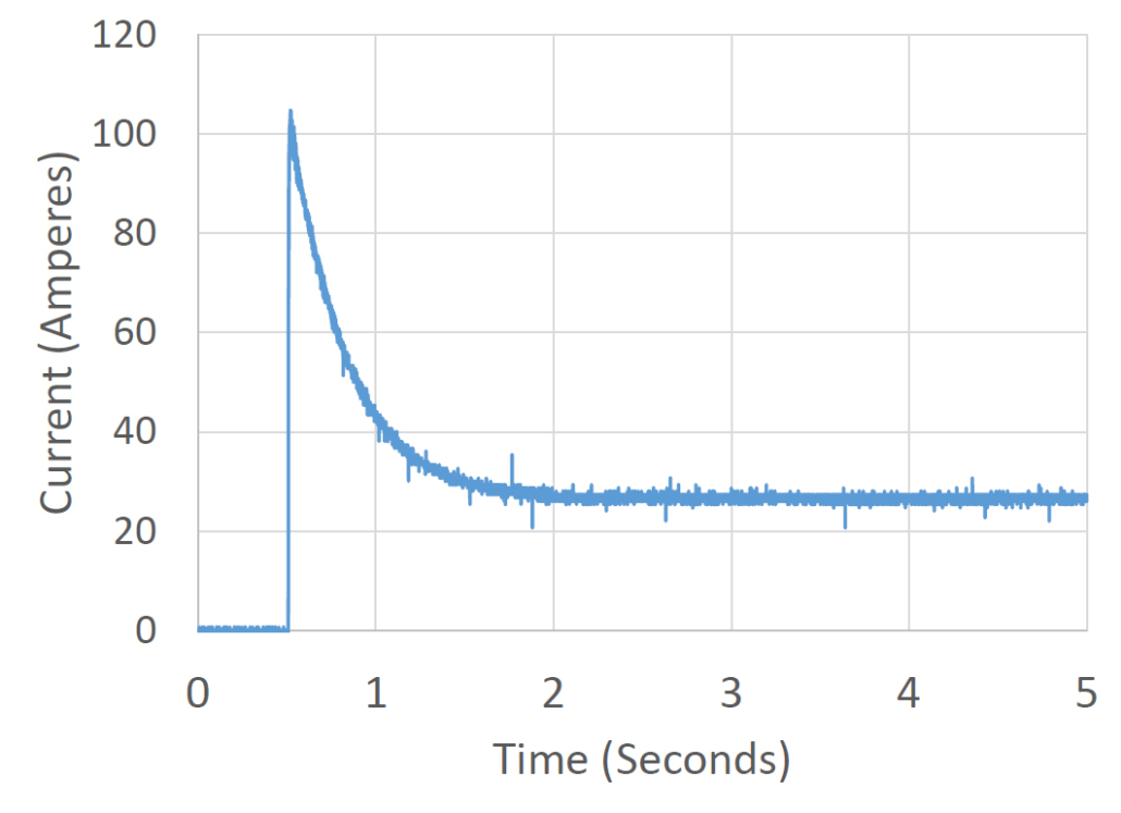
When an electric motor is started, the rotor appears to be stalled at the instant the current is applied.  This stalled current will flow through the motor windings.  As the motor starts to turn, the amount of current flowing to the motor will drop.  When the motor reaches its steady-state speed, the current will level off.  This initial in-rush current can be 4 to 5 times the steady-state current depending on the size of the motor.  The graph below shows an example of this in-rush current.

Graph showing the start-up current of a cooling fan

Graph showing the start-up current of a cooling fan

In the case of this fan motor, the initial in-rush is approximately 100-amps.  Within 2 seconds of starting, the current levels off at about 25-amps.

In most cooling fans, the manufacturer will tell you that you need to use a 70-amp relay to turn the fan on and off.  This is because of the starting current or in-rush current going to the motor.  With your Infinitybox system, you can drive most cooling fans directly without adding an external relay.  The outputs used in the POWERCELL outputs are designed to handle this in-rush current.

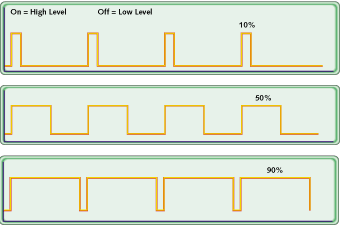
In addition to just handling the in-rush current, we use an extra trick to help manage this in-rush current.  As mentioned above, we don’t use relays on our outputs.  We use MOSFETs.  MOSFETs can be turned on and off thousands of times per second.  You can’t do that with a relay.  This on and off lets us do something called Pulse-Width Modulation or PWM.  There are two important parts of PWM.  The first is the frequency.  This is how many times you turn the MOSFET on and off each second.  Our PWM frequency is 20,000 Hertz.  The second part is duty cycle.  This is the ratio of the on time over the off time.  A 50% duty cycle would have the output on for the same period of time as it is off.  A 100% duty cycle means that the output is on all the time.  A 0% duty cycle means that the output is off.  This picture shows the PWM pulses and different duty cycles.

Examples of three different PWM duty cycles

Examples of three different PWM duty cycles

By changing the duty cycle, we can control the amount of power going to the fan.  The higher the duty cycle, the more power is coming out of the POWERCELL output.  When we turn on a fan, we soft-start it.  This means that we gradually start the fan over about one second.  This minimizes the in-rush current.

We get lots of questions about cooling fans and whether or not they can be driven directly from the POWERCELL.  Most can.  A good rule of thumb is to look at the gauge of wire on the cooling fan.  If it is 14-AWG or less, you can certainly use our POWERCELL directly.  In most cases, the manufacturer of the fan will publish the running current or steady-state current for the fan.  Most commonly used fans in aftermarket applications draw between 8 and 20-amperes.

In some cases, our customers want to use two large fans to cool their engines.  The two fans together would draw more than the 25-amps maximum of a single output.  In this case,  you can use any of the OPEN outputs on your configuration sheet.  OPEN means that there is no specific function assigned to them.  You can use them as auxiliary outputs.  We’ll talk about wiring the cooling fan triggers to the MASTERCELL in a few more posts.

DC fan motors have a direction to them.  One of the fan wires will connect to the POWERCELL output and provide battery power to the motor.  The second wire must be connected to ground.  You must check the manual that came with your fan to determine which wire is power and which is ground.  You can also watch the rotation of the motor.  Most fan manufacturers put an arrow that indicates the correct direction that it should spin.  If the fan spins in the wrong direction, reverse the wires.

You can splice the POWERCELL output wire to the wires on the fan in the same way that we described in our headlight post.  You can get to that post by clicking this link.

Keep watching for updates on this 1967 Mustang wiring job with our 20-Circuit Kit.  If you have questions or comments, you can click on this link to get in touch with our team.

Ignition

In our last post, we talked about wiring the starter solenoid to the POWERCELL in your 20-Circuit Kit.  Now it is time to wire the ignition.  There is a dedicated output on your POWERCELL that supplies battery voltage for your ignition.  This is your “key-on” power.  In this post, we are going to talk about wiring the POWERCELL output.  We’ll discuss wiring the MASTERCELL input to the ignition switch in later posts.

Our Infinitybox system can power any type of ignition system.  It can be a basic set of points or a highly sophisticated EFI system.  In either case, we are going to power the ignition system when the key is on.  In the case of this 1967 Mustang, the customer is using the Ford Coyote Crate Motor with the Ford ECU.

Check the configuration sheet that came with your kit.  It will define which output is for the ignition.  In most cases, it is the light-green wire on the front POWERCELL.  This is output 3 on the B connector.

You need to carefully read the instructions for your ignition system.  In most cases, there will be a wire that needs to connect directly to the battery to give it constant 12-volt power.  There will also be a key-on or ignition power feed.  That will come from the light-green wire on your POWERCELL.  Over the years, we have accumulated many different wiring diagrams for different ignition systems.  They can be found in posts on our blog or in our reference library.  We’ll highlight some of the most popular in this post.

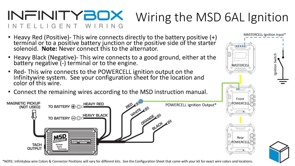
The most common ignition system that we see customers using is a ignition box from MSD.  The MSD 6A or 6AL are some of the most popular.  There is a heavy red and heavy black wire in their harness.  These wires need to connect directly to the battery and to chassis ground, respectively.  Then there is a lighter gauge red wire that is for the key-on power.  This will connect to the ignition output on your POWERCELL.  See the picture below for more details.

Image of wiring diagram showing how to wire the MSD 6A with the Infinitybox system.

Image of wiring diagram showing how to wire the MSD 6A with the Infinitybox system.

This link will take you to a blog post talking in more detail about wiring an MSD ignition box to our POWERCELL.

We also have many different posts that talk about how to wire the ignition outputs to EFI systems.  This picture shows wiring our ignition outputs to the FAST EZ-EFI system.

Picture of wiring diagram showing how to wire the FAST EZ-EFI fuel injection system with the Infinitybox system.

Picture of wiring diagram showing how to wire the FAST EZ-EFI fuel injection system with the Infinitybox system.

Our ignition output from the POWERCELL connects to the pink wire in the EZ-EFI harness.  You can read the entire blog post on the FAST wiring at this link.

Another popular option for our customers is the Holley Dominator EFI system.  This link shows you a picture of how to wire that into our system.

Image of wiring diagram showing how to wire the Holley Dominator EFI System with the Infinitybox System.

Image of wiring diagram showing how to wire the Holley Dominator EFI System with the Infinitybox System.

In the case of our customer’s 1967 Mustang, they are using the Ford Coyote crate engine for this car.  We have a complete schematic that shows you how to connect the ignition output from the POWERCELL to the ECU.  You can see that schematic at this link.

Once you have your ignition system or EFI system wired to the ignition output, you also have to think about the other things that you want to come on with your ignition switch.  Remember that each POWERCELL output has the capacity of 25-amps.  You can use this single output to power many different functions.  You are going to use this same ignition output to power your gauges, your transmission controller, your radio power or any other function that you need to power with ignition.

In earlier posts in this series, we talked about how to splice off of POWERCELL outputs for multiple taps.  These examples included your headlights, high-beams and parking lights.  For your ignition, we recommend creating a ignition bus that you can use to power the many different switched functions in your car.  You can use a terminal strip to create a common point for your ignition functions.

You can purchase terminal strips like this from companies like Del City and Waytek Wire.  Make sure that you pick a terminal strip that has an insulating cover on it.  You want to make sure that you protect these wires from getting shorted to ground.

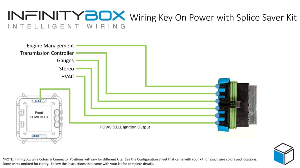
Another option is to use our Infinitybox Splice Saver Kit.  This is a simple accessory that makes connecting a POWERCELL output to multiple wires robust and reliable.  This picture shows you how you can use the Splice Saver Kit to create a sealed junction point for everything that needs to get powered off of your ignition.

Wiring ignition key-on power with the Infinitybox Splice Saver Kit

Wiring ignition key-on power with the Infinitybox Splice Saver Kit

Please contact us with questions about wiring the ignition output on your Infinitybox system.  Click this link to reach out to a member of our team.


Starter Motor

Next in our wiring series, it is time to wire the starter motor.  There are a few important things that need to be considered when you do this.  In this post, we are just talking about connecting the POWERCELL output to the starter solenoid.  In later posts, we will go through the details for wiring the ignition and starter switch.

There is a dedicated output on the front POWERCELL for the starter solenoid.  In most kits it is the light-blue wire, which is output 4 on the B connector.  When you turn on the MASTERCELL input for the starter, you get power on this starter wire.  This energizes the starter solenoid coil.

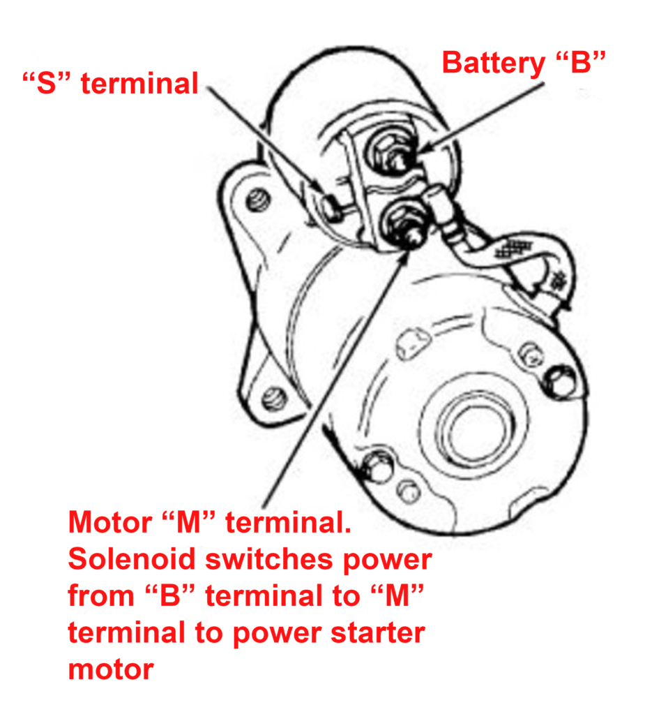
There are two main types of starter motors.  Some have the starter solenoid built into them.  Others rely on an external starter solenoid.  It takes hundreds of amperes to crank an engine.  Your battery is the source of this current.  It takes a special solenoid to repeatedly switch this high current.  A normal relay can’t carry this amount of current.  You need a solenoid.  This picture shows you the details of a typical starter motor with a built-in solenoid.

Drawing of the anatomy of a starter motor

Drawing of the anatomy of a starter motor

The starter solenoid gets a direct connection from the battery.  This will supply the starting current when you turn on the starter.  There is also a contact on the starter solenoid that connects to the starter output on the POWERCELL.  When you turn the key to the start position, battery voltage is applied to this start terminal.  This voltage does two things.  The solenoid pulls in which pushes the Bendix out to engage with the engine flywheel.  It also closes a large set of high-current contacts within the solenoid that lets current flow from the battery to the starter motor.  This current spins the motor, which turns the flywheel.

When you release the key from the start position, the battery voltage is removed from the start terminal on the solenoid.  This opens the contacts providing current to the motor, so the motor stops spinning.  Also, the Bendix retracts from the flywheel.

This picture shows a typical wiring diagram for a starter motor with a built-in solenoid.

Starter motor drawing showing different electrical connections

Starter motor drawing showing different electrical connections

The B terminal connects directly to the battery.  We’ll discuss this in more detail below.  The M terminal is internally connected to the windings on the starter motor.  The S terminal is what connects to the starter output on the POWERCELL.  When there is battery voltage from the POWERCELL on the S terminal, the solenoid engages.  The Bendix extends into the flywheel and the B terminal gets connected to the M terminal.  This provides the current to turn the starter motor.  The starter motor gets grounded to the chassis through its mounting plate to the engine block.

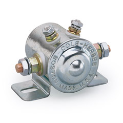
There are other starter motors that do not have the built-in solenoid.  They use a different mechanism to extend the pinion into the flywheel.  They rely on an external solenoid to switch the current to the starter motor.  This picture shows an example of an external solenoid.

Cole Hersee Solenoid

Cole Hersee Solenoid


This external solenoid is what switches the high-current for the starter motor.  One of the large terminals connects to the starter motor.  The other large terminal connects directly to the battery.  Again, we’re going to talk about this battery connection below.  One of the small terminals needs to get connected to ground.  The other small terminal needs to get connected to the starter output on the POWERCELL.  When the POWERCELL applies battery voltage to to the starter terminal, the solenoid closes and lets current flow to the starter motor, which turns the flywheel.

Now it is time to talk about the battery cable.  This is what supplies current from the battery to the starter motor.  At the instant you close the starter solenoid, the current flowing to the starter motor can be between 1,500 to 2,000 Amps.  Once the engine starts to turn, that current will drop down to 200 to 400-Amps.  You must make sure that you size this cable appropriately.  A lot of guys get cheap with their battery cables and go with smaller gauges.  This is a case where the bigger, the better.

We recommend using a 1/0 or 2/0 welding cable to connect the battery to the starter.  Smaller cables will result in voltage drop to the starter.  Voltage drop will lead to problems starting the engine.  Welding cable is much more flexible and easier to work with than typical battery cables.  It is easier to route through the car.  Please note that we do not include the battery cable or the required ring terminals in our kit.  You need to source these separately.

You also need to consider the grounds between the engine block and the chassis.  Whatever current flows to the starter has to return to the chassis.  You need to have good and large ground straps between the engine block.  The size of the ground cables must be equal or greater than the size of the cable you have feeding the starter.

Please click on this link to contact our team with questions about wiring the starter output on the POWERCELL in your 20-Circuit Kit.


Hazard Lights

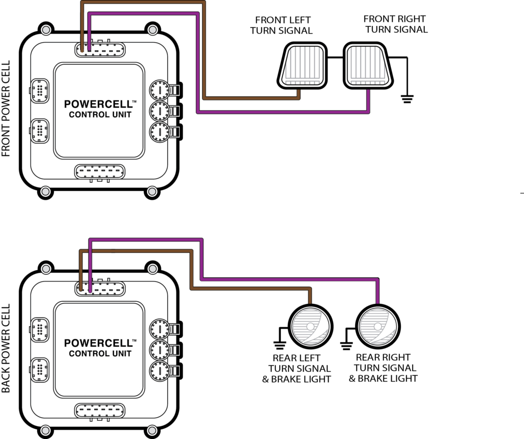
We just posted details on how to wire your turn-signal and brake lights to our Infinitybox POWERCELLs.  Here’s a quick follow up to that post.  Once you have your turn-signal outputs wired, wiring your hazard lights is really easy.

Some people call them hazard lights, hazard warning flashers, warning lights, emergency lights, 4-way flashers or simply flashers.  Whatever you call them, these are the flashing lights in the corners of your car that you turn on when you help or when you want to warn other drivers.

In most cars, your hazard lights are simply your turn signals.  The original mechanism in the steering column shunted all of the turn signal bulbs together through the flasher can when you pressed the hazard button.  With our Infinitybox system, you simply turn on an input to the MASTERCELL for the hazard lights.  The MASTERCELL sends a command to the front and rear POWERCELLs to flash the left and right turn signals together.  You do not need a separate flasher can, the POWERCELLs handle that for you.

Wiring diagram for 1-filament brake lights and turn signals for the Infinitybox system.

Wiring diagram for 1-filament brake lights and turn signals for the Infinitybox system.

If you look at the line in your configuration sheet for the hazards, you will see that there is a dedicated input going to the MASTERCELL.  You will also notice that the POWERCELL outputs are just the turn signal outputs on the front & rear POWERCELL.  This picture shows the hazard lights details from our standard front-engine configuration.

Configuration details for wiring 4-way flashers with the Infinitybox system

Configuration details for wiring 4-way flashers with the Infinitybox system

If you need it, you can get more information on how to read our configuration sheets by clicking this link.

We’re going to talk about wiring inputs in upcoming posts.  For now, everything that we need to do for the hazard lights in our 1967 Mustang is done since we wired the turn signals.

If you have questions or comments about wiring any parts of your car, truck or commercial vehicle with our Infinitybox system, please click this link to contact our team.