Wiring a Cooling Fan

We recently blogged about how you connect the Infinitybox MASTERCELL to the Holley Dominator ECU.  The next thing that most guys ask about is how to wire a cooling fan.  With the Infinitybox 10 and 20-circuit Harnesses, this is very easy.

Remember that the POWERCELL acts like the fuse and relay box.  Built in the cell is the switching device, called a MOSFET, that turns the output on and off.  It also includes a fuse to protect the wiring harness against short circuits or other over-current events.  You can use the Infinitybox system to control your cooling fan and in most cases, you can eliminate the need for a relay and separate fuses.

The cooling fan must turn on when the engine temperature reaches a set point.  When the engine temperature cools down, the fan should turn off.   There are two main ways to do this.  Traditionally, you have a thermostatic switch in the radiator or modern ECUs have their own temperature sensors to trigger the fan.

In the first case, you are installing a thermostatic switch into the radiator or the engine block.  Most of these switches have a single terminal on them.  They have a mechanism built inside that electrically connects that single terminal to its case when it reaches a set temperature.  This case is connected to ground by being screwed into the radiator or the engine block.  When the temperature drops, the electrical connection between the single terminal and ground is broken.

The MASTERCELL inputs work by being connected to ground.  To wire the MASTERCELL input to the thermostatic switch, simply connect the input wire for the cooling fan to the terminal on the switch.  See the configuration sheet that came with your kit for the right wire color and connector.

Once you have the input connected to the MASTERCELL, connect the cooling fan output on the POWERCELL to one wire on the cooling fan motor.  The other wire needs to connect to the chassis for ground.  We recommend using a 25-amp fuse in the POWERCELL output to protect this wire.

This picture shows in detail how you connect the MASTERCELL input to the temperature switch and how to connect the POWERCELL output to the cooling fan motor.  You can also download a PDF of the wiring diagram here.

Image of wiring diagram showing how to wire a thermostatic cooling fan switch to the Infinitybox MASTERCELL

Image of wiring diagram showing how to wire a thermostatic cooling fan switch to the Infinitybox MASTERCELL

Most ECU’s have a trigger that is used to control the cooling fan.  They have a sensor that measures engine temperature and they use an external trigger to turn the fan on and off.  These cooling fan triggers can either ground switch the cooling fan or they can positive switch the trigger.  The manual for the ECU will describe whether the trigger is ground switched or positive switched.

As described above, the MASTERCELL inputs work by being pulled to ground.  When the ECU ground switches the cooling fan trigger, it internally grounds the wire when it wants the fan on.  In some cases, the voltage on this trigger may float or get pulled to battery voltage when the cooling fan is supposed to be off.  This voltage needs to be blocked from flowing back  into the MASTERCELL input.  To do this, solder a diode in series between the MASTERCELL input and the trigger wire on the ECU.  The recommended diode is a 1N4001 and can be easily purchased on-line.  When installing the diode, the stripe on the diode should face towards the trigger wire on the ECU.  This will not work correctly if the diode is wired in backwards.

If the cooling fan trigger on the ECU positive switches the cooling fan signal, you need to invert this to a ground trigger for the MASTERCELL.  You can do this with a relay.  This link will take you to a diagram showing how to do this.

The easier way to convert the positive switch signal from the ECU to a ground switched signal is to use one of our inVERT Mini modules.  These are small and fit easily into the harness.  This link will take you to more information on the inVERT Mini.

Once you have the MASTERCELL input wired to the trigger on the ECU, you need to wire the POWERCELL output to the fan.  This is done exactly the same way as described above for the thermostatic switch example.  Connect the cooling fan output on the POWERCELL to one wire on the cooling fan motor.  The other wire needs to connect to the chassis for ground.  We recommend using a 25-amp fuse in the POWERCELL output to protect this wire.

This picture shows in detail how you connect the MASTERCELL input to the ECU and how to connect the POWERCELL output to the cooling fan motor.  You can also download a PDF of this wiring diagram at this link.

Image of wiring diagram showing how to wire the cooling fan trigger from an ECU to the Infinitybox MASTERCELL

Image of wiring diagram showing how to wire the cooling fan trigger from an ECU to the Infinitybox MASTERCELL

Sometimes, a customer may want to have a bypass switch that they can use to turn on their cooling fans.  This is usually a toggle switch on the dash that will turn on the fan at any time, even when the engine is not up to temperature.

In the case where you have a temperature switch, you simply wire the bypass switch in parallel.  This means you splice into the MASTERCELL input wire that is going to the temperature switch.  You connect the splice to one side of the bypass switch and you ground the other side of the switch.  You can see this shown in the wiring diagram for the traditional temperature switch case.

If you’re controlling the fan through the ECU, you do the same thing.  You splice into the MASTERCELL input wire for the cooling fan that is going to the ECU.  You connect the splice to one side of the bypass switch and you ground the other side of the switch.

Please let us know if you have any questions about how you wire your cooling fans with our Infinitybox 10 and 20-circuit harness kits.  You can reach out technical support team at (847) 232-1991 or email us at sales@infinitbox.com.  You can also contact our team by clicking this link.  

Automatic Headlights

We get a lot of questions about adding advanced features to our Infinitybox system. The reality of our system is that it is very easy to add modern functions to your car Here’s another great example.

A lot of customers want to add automatic headlights to their car. Some people call this a twilight function and practically every new car can do this. When it gets dark outside, the headlights turn on automatically.

To do this, you can use practically any light sensor. It just needs to make a connection when the light level gets dark. You are going to use this connection to ground the MASTERCELL input for the headlights. Remember that the MASTERCELL triggers an output on a POWERCELL when the input wire is grounded.

You can find simple photosensor relay modules on-line.  Amazon has a lot of options.  Try searching for “Photosensor Sensor Relay Module”.

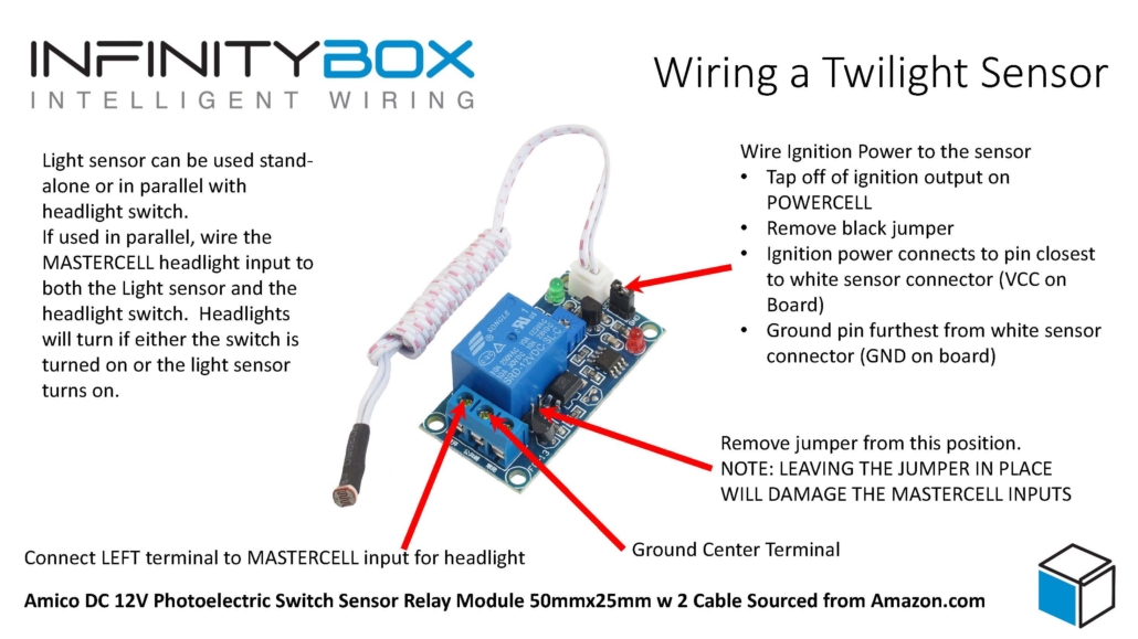
The photoelectric switch simply needs power and ground. You should tap off of the ignition output on your POWERCELL to provide 12-volts to the switch. You can ground it locally in the car. The power and ground terminals are located on the side of the switch close to the white sensor connector. The power terminal is closest to the white connector and it is labeled VCC on the board. The ground terminal is on the side away from the white connector and it is labeled GND on the board.

On the other side of the board is a blue connector. The center terminal of this connector will connect to ground. You can connect this locally to ground or you can use one of the black ground wires in the MASTERCELL harness. There is a black jumper that may be located on a set of pins next to the relay on the board. See the picture below for more details. It is very important that this jumper be removed from the pins. You can do this with your fingernail or a small pair of needle-nose pliers. This jumper selects between ground switching the outputs on the relay or applying 12-volts from the relay. The MASTERCELL inputs are designed to be ground switched and they can be damaged if voltage is applied to them. You must make sure that you remove this jumper from the pins on the board.

Once you have the jumper removed, connect your MASTERCELL input to the left terminal next to the relay. See the diagram below for more details.

Lastly, take the white sensor cable and mount it in a place in the car where ambient light will hit it. You may have to experiment with the location of this sensor. There is also a potentiometer on the board that you can use to adjust the sensitivity of the sensor. Essentially, you need to adjust its location and the potentiometer so that the relay turns on when the ambient light falls below the threshold that you want.

You can have this light sensor as your only way to turn on your headlights. To do this, simply run the headlight input to the MASTERCELL directly to the light switch. You can also have it so that either the light sensor or the headlight switch will turn on your lights. To do this, wire the MASTERCELL input to both the headlight switch and the light sensor. You can split the MASTERCELL input into two runs, one for the headlight switch and one for the light sensor.

Image of a wiring diagram showing how to wire a simple photosensor relay to a MASTERCELL input

Image of a wiring diagram showing how to wire a simple photosensor relay to a MASTERCELL input

This diagram is just an example of one photosensor relay board that we found on Amazon.  Follow the instructions that came with the photosensor that you are going to use.

You can download a simple diagram from our website that shows you all of the details. This link will take you there.


Please give our technical support team a call if you have questions about wiring your twilight lights with this sensor.  You can click on this link to contact our team directly.

10-Circuit vs. 20-Circuit Kits

A lot of people ask: “Do I need a 10 or a 20-Circuit Harness Kit for my car?”  The answer is, it depends. Both the 10 and 20-Circuit Harness Kits use our rock-solid multiplexing technology.  The only difference between the kits is the number of POWERCELLs that you get.  The 10-Circuit Kit gets you one MASTERCELL and one POWERCELL.  The 20-Circuit Kit gets you one MASTERCELL and two POWERCELLs. Each POWERCELL has 10 outputs.  When you sit down and look at the number of things that you have to control in a basic car, you can handle most all of them with the 10 outputs on a 10-Circuit Kit.  This includes things like the starter solenoid, ECU power, headlights, turn signals, parking lights, etc.  Wiring your car with a 10-Circuit Kit can be a lower cost option to get more advanced features in your car.  You have the option to add practically any of our Infinitybox accessories to the 10-Circuit Kit including inLINK for security functions, inTOUCH NET for touch screen control and inMOTION to control windows and power locks. Going up to the 20-Circuit Harness Kit gets you some significant advantages over the 10-Circuit Kit.

  1. The extra POWERCELL gets you 10 more outputs.  This gives you more flexibility to control more things through the Infinitybox system.
  2. Having two POWERCELLs lets you put them where you need them in the car.  With two POWERCELLs, you can place one in the front of the car and one in the rear.  This means that you’re running less wire because you can wire things to the local POWERCELL.  Examples here include the turn signals, which are on the front & rear of the car.  The parking lights are another example since they are in the front and rear of the car.  With the single POWERCELL in the 2-Cell Kit, you have to run all of the wire back to a central location.  With multiple POWERCELLs you have more flexibility and can run less wire.
  3. The extra POWERCELL in the 20-Circuit Kit gets you more flexibility to control your tail lights and turn signals.  A lot of late 1960’s cars use a single filament of one bulb on each side of the car for both the brake lights and the turn signals.  We call this a single-filament configuration.  The filament on each side of the car flashes independently as a turn signal or both sides turn on together when you step on the brake lights.  The 20-Circuit Kit is set up to manage this turn-signal and brake light function within Infinitybox.  You can’t do this directly with the 10-Circuit Kit because you only have one set of outputs for the turn-signals spliced to the front and rear of the car.  If you did this with the 10-Circuit Kit, your front turn signals would turn on when you stepped on the brake pedal.  There is a fix for the 10-Circuit Kit in a car that needs a single-filament configuration that involves a trailer converter.  Give our tech guys a call if you want to go this way.

The other thing to consider is that the 10-Circuit Kit may not get you all of the outputs that you need to make your car street legal.  Talk to our team to verify.

We have a configuration sheet specific for the 10-Circuit Kit.  Click on this link to see it.  This link will take you to an example of one of our 20-Circuit Harness Kit configurations.  This one is for our front-engine set up. At the end of the day, you can wire a basic car easily with our 10-Circuit Kit.  You get all of the benefits and add-on capability of the entire Infinitybox system.  However, adding the extra POWERCELL expands the flexibility of the system significantly. Click here to contact our team with any additional questions.  

Picture of the Littelfuse Minifuse

Why A Fuse?

We get this question a lot.

Why do the POWERCELL and inMOTION cells use fuses to protect the outputs?  Some say that we’re already using smart MOSFETs, why not rely on them to protect against over-current on the output wires?  Others ask, why not use circuit breakers?  There are several important and practical reasons why we rely on a traditional fuse to protect the outputs on our Infinitybox hardware.

With respect to MOSFETs, they are tried and true technology.  They are used in practically every application for switching and current control.  The MOSFETs used in the POWERCELLs are automotive-grade and designed to carry up to 270-amps.  The chances of them failing in a typical customer car are minute.  However, if a MOSFET fails, it doesn’t fail gracefully.  If a MOSFET were to fail, it fails resistive.  That means that they are going to generate a significant amount of heat, quickly.  No intelligence built into the circuitry can interrupt the current flow if the silicon die in the MOSFET package has become a resistor.  In that case, the fuse is your last line of defense to protect the system from thermal runaway.

You can use the same logic for inMOTION.  It has sensors on the board that monitor the total amount of current flowing out to the load.  inMOTION already shuts off the relay coils when it sees too much current, why not rely on that alone without the fuses?  The practical reality is that a common failure mode for relays is for the contacts to weld together, especially in inductive motor application.  If this were to happen, no intelligence on the inMOTION board can open the circuit.  Again, the fuse becomes the last line of defense.

With the above being said, you can see the need for some circuit protection component in the system if other components fail.  That leads to the debate between fuses and circuit breakers.  Circuit breakers can certainly do the job, however a fuse will out perform a breaker in all categories.

  1. Fuses are more cost effective than circuit breakers.
  2. Fuses are smaller and package better than circuit breakers.
  3. Fuses have better low-overload protection characteristics than circuit breakers.  This is very important in cases of resistive shorts like a failed MOSFET.
  4. Fuses respond quicker than circuit breakers under short-circuit conditions.

Most importantly, a fuse drives better end user behavior than a circuit breaker.  At the end of the day, there is a reason why a fuse opens or a breaker trips.  A motor has failed.  Insulation on a wire has shorted to ground.  An electronics module has failed.  In all these cases, you do not necessarily want to blindly reset a breaker and keep on driving.  The cause of the over-current condition needs to be identified and fixed before resuming normal operation of the vehicle or equipment.  Otherwise, more severe thermal events can occur in the wiring harness causing damage or injury.

See our blog for additional posts on proper fusing and other circuit protection lessons.  If you have any questions, reach out to our power distribution experts at (847) 232-1991 or email our team at sales@infinitybox.com.  You can also click this link to contact our team directly.