Wiring Dakota Digital VHX Gauges
Dakota Digital has been in the business of making advanced electrical products for the Automotive Aftermarket for a long time. Their products include gauges, lighting, cruise control systems, gear indicators, linear actuators, climate control interfaces and other automotive accessories. We’ve posted details before on how to wire their cruise control systems and their automatic door lock module. Their VHX series of gauges has become very popular in the market and a lot of our customers have asked about how to connect their VHX gauge controller box to our Infinitybox system. This blog post is going to walk you through the details of Wiring Dakota Digital VHX Gauges to our system.
If you are using the RTX gauges, you can click on this link to get to a wiring them.
Before we go too far, this post is only going to cover wiring primary power, ground, key-on power and the signals for the indicators on the dash. Their manual will cover the details for the rest of the wiring. Carefully read and understand all of the details of the VHX instructions before you go any further. You can get their manual by clicking this link.
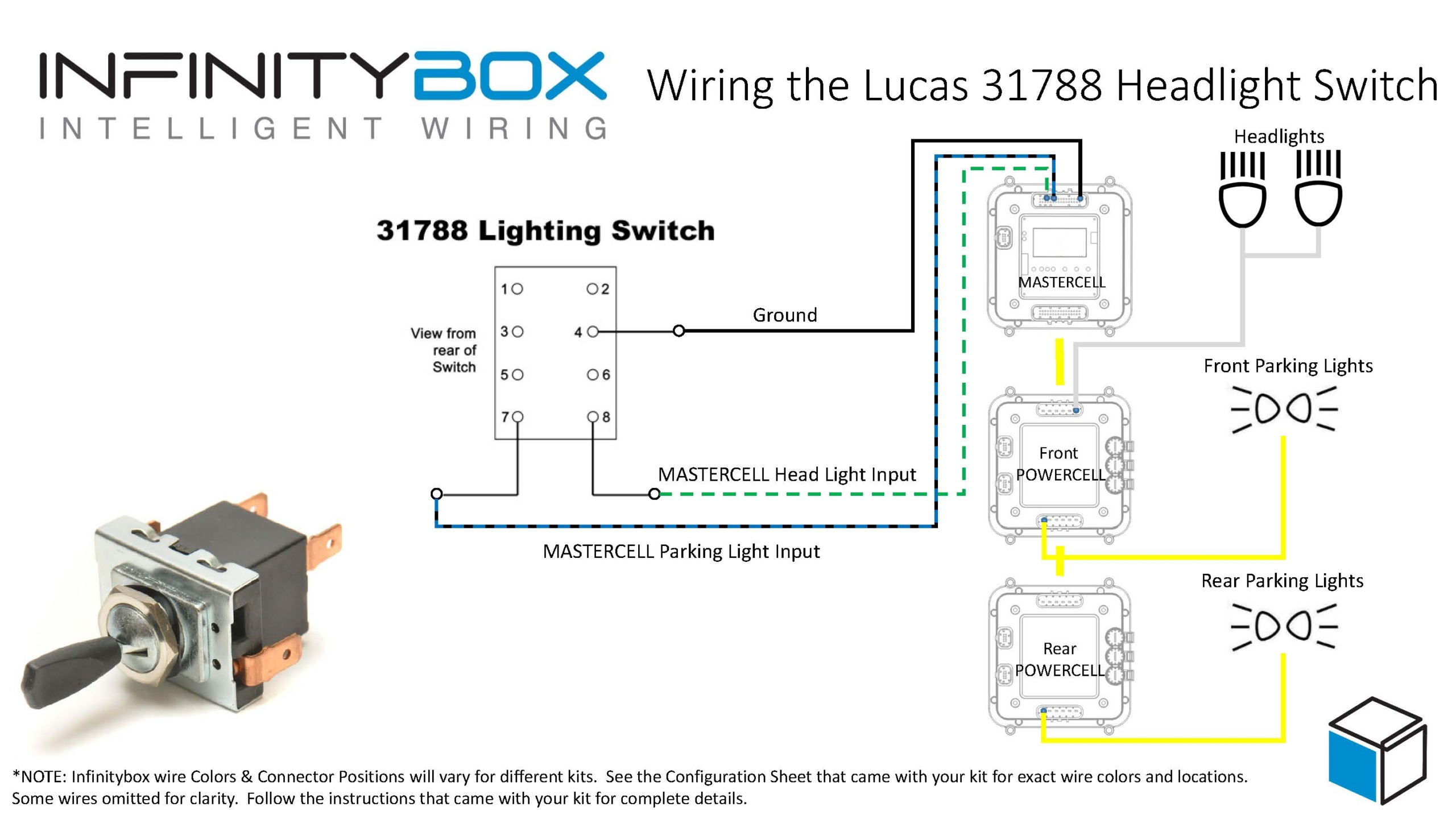
This diagram shows an overview of the connections to the Infinitybox system for the VHX controller box.

Picture of wiring diagram showing you how to interface your Dakota Digital Gauges with the Infinitybox 20-Circuit Kit
Their VHX controller needs constant power from the battery. Connect the CONST. POWER terminal on their controller box directly to the positive terminal on the battery. You must fuse this wire at the battery for safety. You also have to connect the GROUND terminal on their controller box to a good chassis ground connection. This must be a metal-to-metal connection that is free of paint, powder coating, dirt and debris.
Here are the connections that are specific to the Infinitybox system.
First, the VHX controller box needs ignition or key-on power. This is what turns the gauges on when you turn the key in the car. Your ignition output is going to provide this power. In most systems, this output is number 3 on the front POWERCELL. Check the configuration sheet that came with your kit to confirm. This ignition output is going to power your engine management. You are going to splice into this wire to connect to the ACC. POWER terminal on the VHX controller box.
Next, you need to connect your parking light output on the front POWERCELL to the DIM(+) terminal on the VHX controller box. This will turn on the illumination on the VHX gauges when you have your parking or headlights on. Just like the ignition output, splice into the parking light output on your front POWERCELL and connect this to the DIM(+) terminal.
Lastly, you need to connect the POWERCELL outputs for your turn signals and high-beam to their respective terminals on the VHX control box for the turn signal indicators and high beam indicator. Just like the key-on power and parking lights, splice into the output wires for the left turn signal, right turn signal and high-beams and connect them to the LEFT(+), RIGHT(+) and HIGH(+) terminals, respectively. When your POWERCELL is flashing the left turn signal, the indicator for the left turn signal will flash on the Dakota Digital gauges. When you have your high beams on, your high beam indicator will light up on the gauges.
Our Infinitybox system can power any electrical system in your resto-mod, street rod, pro-touring build or race car. Wiring Dakota Digital VHX Gauges is a great example of that. You can download a PDF of this wiring diagram by clicking this link.
Our technical support team is available to answer any questions about blog post or any other topics about wiring your car with our Infinitybox system. Click on this link to get in touch with our team.


 Copyright Infinitybox, LLC 2021. All Rights Reserved.


 Copyright Infinitybox, LLC 2021. All Rights Reserved.


 Copyright Infinitybox, LLC 2021. All Rights Reserved.