
 Copyright 2026 Infinitybox, LLC. All Rights Reserved.
Haltech Nexus S3 ECU Wiring Diagram
One of the most common questions we get is whether the Infinitybox system works with a customer’s ECU or EFI system. It does. In this post, we show how to wire the Haltech Nexus S3 ECU to either our Legacy System or our IPM1 Next Generation Kit.
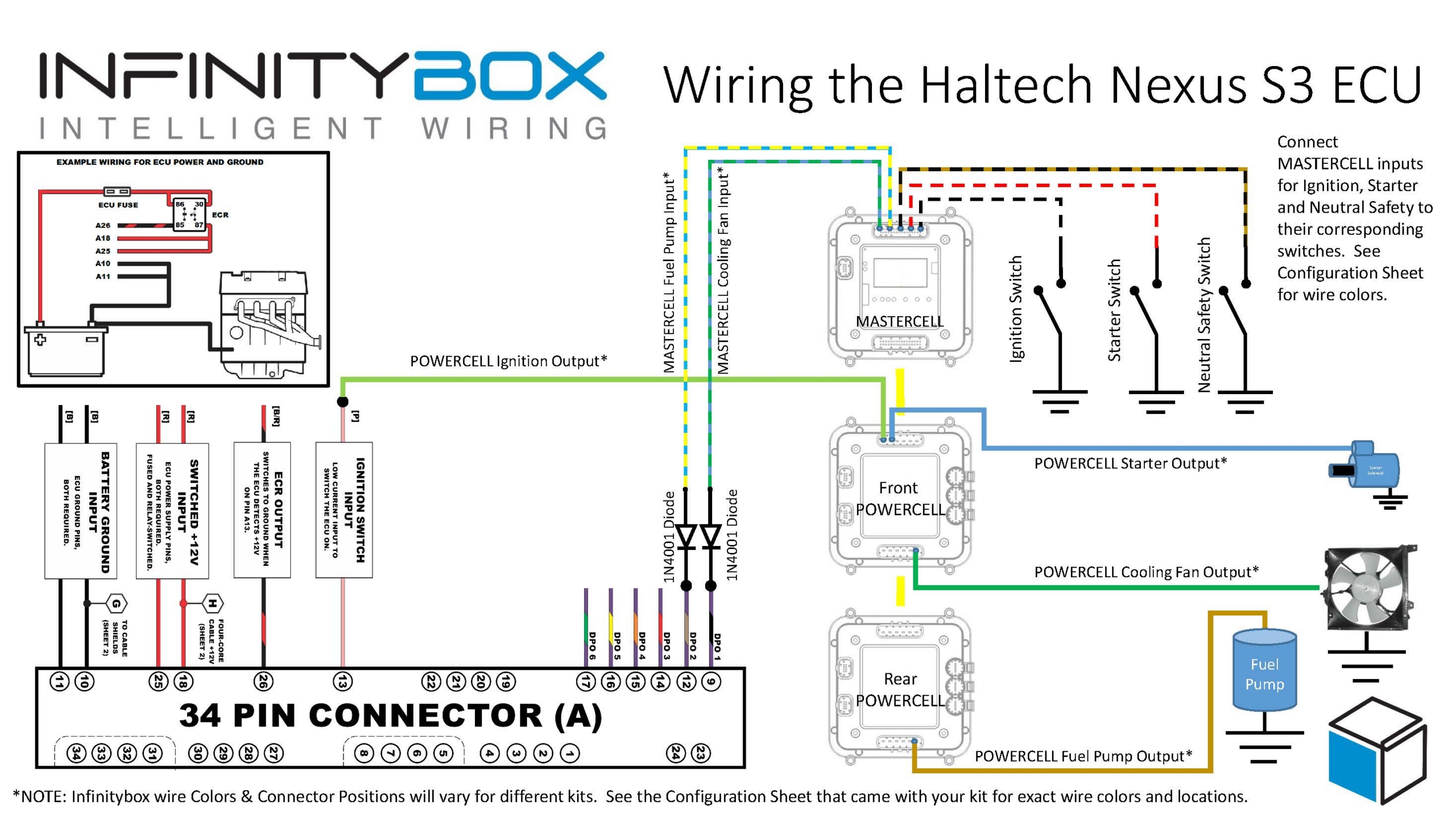
Wiring the Haltech Nexus S3 ECU to the Infinitybox system. Wire colors and connector positions vary by kit, so check your Configuration Sheet.
Before You Start
Please read the Haltech Nexus S3 manual carefully and follow Haltech’s instructions for wiring ECU power, ground and all other connections to the engine. This post only shows how to do two things: connect ignition power to the ECU, and connect the triggers for the cooling fan and fuel pump.
The diagram also reproduces Haltech’s example for ECU power and ground, with the fuse, Engine Control Relay (ECR) and connections on pins 10, 11, 18, 25 and 26, for reference. Wire those connections as the Haltech manual describes.
Wire Colors and Connector Positions
Infinitybox wire colors and connector positions vary from kit to kit. Always use the Configuration Sheet that came with your kit for the exact wire colors and locations. This is especially important for the cooling fan output and the MASTERCELL inputs, which differ between the Legacy System and the IPM1 Next Generation Kit.
Ignition Power to the ECU
The Nexus S3 turns on through its ignition switch input, pin 13 on the 34-pin Connector A. This is a low-current input, and the signal must stay active in both the Run and Start positions so the ECU stays powered while the engine cranks.
Connect the front POWERCELL Ignition output to pin 13 on Connector A. The ignition, starter and fuel pump POWERCELL outputs are the same on the Legacy System and the IPM1 Next Generation Kit.
Fuel Pump and Cooling Fan Triggers
The Nexus S3 doesn’t have fixed outputs for the fuel pump and cooling fan. You select and program the Digital Pulsed Outputs (DPOs) that control them in Haltech’s NSP software. Each DPO can be set up as a ground trigger or a positive trigger. We recommend ground triggers, and they work with both the Legacy System and the IPM1 Next Generation Kit.
Our diagram uses DPO 1 and DPO 2 as examples. Use whichever DPOs you assign to the fuel pump and the cooling fan:
- Run the wire from the DPO you assigned to the fuel pump through a 1N4001 diode to the MASTERCELL fuel pump input.
- Run the wire from the DPO you assigned to the cooling fan through a 1N4001 diode to the MASTERCELL cooling fan input.
Each signal needs its own diode to isolate it, and the diode orientation matters. Match the direction shown in the diagram. Set both DPOs as simple on/off outputs, not pulsed ones.
The POWERCELLs do the heavy lifting by switching the fuel pump and cooling fan, so no external relays are needed. Connect the MASTERCELL inputs for the ignition, starter and neutral safety switches to their corresponding switches. See your Configuration Sheet for the wire colors.
Resources
Questions?
If you have questions about wiring the Haltech Nexus S3 to your Infinitybox system, contact us, email sales@infinitybox.com, or call (847) 232-1991.