How to Enable inRESERVE with the MASTERCELL NGX

Table of Contents

The Problem: Battery Drain on Modern Classics

Classic cars were simple. An old car with mechanical switches and a set of points had practically no draw from the battery when the ignition was off. The car could sit in a garage for months with no issues. As our customers add computer-controlled EFI systems, audio systems, alarms and our Infinitybox system, the steady-state draw from the battery increases significantly. If the car sits for an extended period, that draw can drain the battery to the point where it will not start. Deep discharging is also detrimental to battery life, shortening the overall lifespan of the battery.

Our inRESERVE Active Battery Management System solves this problem by protecting your battery in two ways. First, it always preserves enough stored energy in the battery to crank the engine and get your car started. Second, it protects the battery from being deep-cycled. Deep cycling a battery can cause permanent damage and dramatically shorten its lifespan. inRESERVE monitors the battery voltage when the ignition is off and disconnects the battery before either of these becomes an issue. This post shows you how to enable inRESERVE on the MASTERCELL NGX in your IPM1 Kit.

How inRESERVE Works

The inRESERVE kit includes a latching solenoid that sits between the battery and the rest of the electrical system. The solenoid is a simple mechanical device — the intelligence is in the MASTERCELL NGX. When the ignition is off, the MASTERCELL NGX continuously monitors the battery voltage. If the voltage drops below the threshold for longer than the configured time period, the MASTERCELL NGX commands a POWERCELL output to send a momentary pulse to the solenoid. That pulse latches the solenoid open, disconnecting the battery from the rest of the system and preserving the remaining charge.

The inRESERVE kit also includes a momentary push button. If you know your car will be sitting for a while, you can press the button to manually disconnect the battery before the voltage drops. When you are ready to drive again, press the button to reconnect the battery and you are good to go.

Legacy Kit vs. IPM1 Kit

With our legacy 20-Circuit Kit, inRESERVE had to be pre-programmed on the MASTERCELL at the factory. If a customer ordered inRESERVE with their kit, we configured the MASTERCELL before it shipped. If they decided to add inRESERVE later, we had to reprogram their MASTERCELL to enable the feature. This meant extra lead time and coordination.

The IPM1 Kit eliminates that dependency entirely. The MASTERCELL NGX lets you enable inRESERVE yourself, right from the inSIGHT display. You choose the POWERCELL, the output, the timing and the voltage threshold — all without any factory involvement. You can add inRESERVE to your system whenever you are ready.

Before You Start

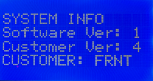
To enable inRESERVE, your MASTERCELL NGX must be running software version 1.3 or higher. If you are not sure which version you are running, follow the steps in our How to Check the Software Version on Your MASTERCELL NGX post to find out.

You will also need your IPM1 Kit configuration sheet so you can identify which POWERCELL outputs are available for inRESERVE. The available outputs are the OPEN outputs on your configuration sheet. These are universal and auxiliary outputs that are not assigned to fixed functions like turn signals, ignition or starter.

Step 1: Open the inRESERVE Menu

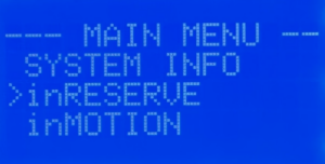
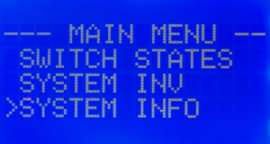
Press and release the HOME button on the MASTERCELL NGX to bring up the Main Menu. Use the SCROLL UP and SCROLL DOWN buttons to move the cursor to the inRESERVE option. Press and release SELECT.

Step 2: Enable inRESERVE

The next screen gives you the option to enable or disable inRESERVE. By default, inRESERVE is disabled. Use the SCROLL UP and SCROLL DOWN buttons to move the cursor to ENABLED. Press and release SELECT.

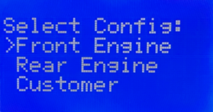
Step 3: Select the POWERCELL

Next, you need to select which POWERCELL will control the inRESERVE solenoid. You will see options for Front PC, Rear PC and Powercell 3. Choose the POWERCELL that is closest to where the solenoid and battery are located in your car. If the battery is in the trunk, select Rear PC. If the battery is under the hood, select Front PC. The Powercell 3 option is only used for custom configurations developed with our team.

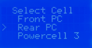
Use the SCROLL UP and SCROLL DOWN buttons to move the cursor to the POWERCELL you want. Press and release SELECT.

Step 4: Select the Output

The MASTERCELL NGX will show you the available POWERCELL outputs based on which cell you selected in the previous step. These are the OPEN outputs on your configuration sheet. In the standard front-engine configuration, the available outputs on the Front POWERCELL are outputs 7, 8, 9 and 10. On the Rear POWERCELL, the available outputs are 4, 5, 6, 7, 8 and 9.

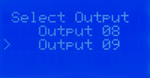
Use the SCROLL UP and SCROLL DOWN buttons to move the cursor to the output you want to use for inRESERVE. Press and release SELECT.

Step 5: Select the Time

Next, you need to select the time delay. This is the amount of time that the battery voltage must remain below the threshold before inRESERVE activates and disconnects the battery. Your options are 15 minutes and 20 minutes. The default is 15 minutes and we strongly recommend keeping this setting. This gives enough time for brief voltage dips during normal operation without triggering a disconnect.

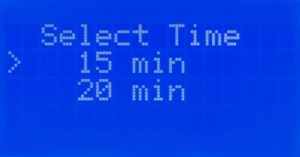
Use the SCROLL UP and SCROLL DOWN buttons to move the cursor to the time you want. Press and release SELECT.

Step 6: Select the Voltage Threshold

The last setting is the voltage threshold. This is the battery voltage level that triggers the time delay. When the ignition is off and the battery voltage drops below this threshold, the countdown begins. Your options are 12.2V and 12.3V. We strongly recommend 12.2V. This is the standard threshold that we used on our legacy kits and provides the right balance between protecting the battery and avoiding unnecessary disconnects.

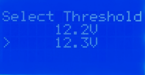
Use the SCROLL UP and SCROLL DOWN buttons to move the cursor to the voltage threshold you want. Press and release SELECT. Your inRESERVE settings are automatically saved when you press SELECT on this final screen.

Wiring the inRESERVE Solenoid

Once you have enabled inRESERVE on the MASTERCELL NGX, you need to wire the solenoid. The inRESERVE kit includes everything you need: the latching solenoid, a MEGA fuse and fuseholder, a momentary reset button, an inline fuse holder with a 10-amp fuse, ring terminals, terminal boots and 14 AWG wire. Download the inRESERVE wiring schematic for the complete wiring details. Do not run the starter current through the solenoid.

Make sure that the reset button is mounted in an accessible location. When inRESERVE disconnects the battery, the car will have no power. You need to be able to reach the button to reconnect the system. The button included with the kit can be replaced with any momentary button rated to at least 7A at 12V.

Questions?

If you have any questions about how to enable inRESERVE or anything else about your Infinitybox system, our technical support team is here to help. Give us a call at (847) 232-1991 or fill out our contact form and we will get back to you.

How to Select Your IPM1 Kit Configuration

Table of Contents

What is the IPM1 Kit Configuration?

Every IPM1 Kit ships with a base configuration loaded on the MASTERCELL NGX. This configuration is the roadmap that you use to wire your car. It identifies each MASTERCELL input wire, its function and the POWERCELL outputs that it controls. This includes all of the key electrical functions in your car like ignition, starter, turn signals, headlights, parking lights, horn, fuel pump, cooling fans and more.

The configuration sheet is the document that details all of these assignments. It shows you the MASTERCELL input wire colors, the POWERCELL output wire colors and the personalities assigned to each output. This link will take you to an example of the front-engine configuration for the IPM1 Kit. You can learn more about how to read the configuration sheet and understand the POWERCELL output assignments by clicking this link. You should keep your configuration sheet handy throughout your entire wiring project. It is the single most important reference document for your build.

About 95% of our customers use the stock configuration with no changes. For those who need to make modifications, our inCODE NGX programming tool lets you customize your configuration to meet the specific needs of your project.

Front-Engine vs. Rear-Engine Configurations

The IPM1 Kit has two core configurations: front-engine and rear-engine. The main difference between these two configurations is where the ignition and starter outputs are located.

In the front-engine configuration, the ignition and starter outputs are on the front POWERCELL. This makes sense for most builds because the engine is in the front of the car and the POWERCELL that is closest to the engine handles the ignition and starter.

In the rear-engine configuration, the ignition and starter outputs move to the rear POWERCELL. This is the right choice if you are building a mid-engine or rear-engine car like a Factory Five GTM or a Race Car Replicas SL-C. In these builds, the engine is behind the driver and the rear POWERCELL is closest to the engine.

Most of our customers are building front-engine cars, so the IPM1 Kit ships with the front-engine configuration loaded by default. If you are building a mid-engine or rear-engine car, you can easily change this yourself right from the MASTERCELL NGX.

Legacy Kits vs. the IPM1 Kit

With our legacy 20-Circuit Kit and 3-Cell Kit, we had to pre-program the configuration at the factory before shipping it to you. If you needed a rear-engine setup, you had to let us know when you placed your order and we would program the kit accordingly.

The IPM1 Kit puts this control in your hands. You can select your IPM1 Kit configuration directly from the MASTERCELL NGX without needing to contact us or send anything back. This is a big improvement in flexibility. If you change your mind about your build or want to start fresh, you can reload a configuration yourself at any time.

Please note that this process only works for the MASTERCELL NGX module that comes with the IPM1 Kit.  It will not work for the Legacy MASTERCELL that came with the 3-Cell kit or the 20-Circuit Kit.  Contact our technical support team if you need support for these legacy systems.  

How to Select Your IPM1 Kit Configuration

The MASTERCELL NGX has three buttons on the front of the unit: SELECT, SCROLL UP and SCROLL DOWN. You will use these buttons to select your IPM1 Kit configuration. Here are the steps to follow.

Step 1 — Start with the system powered off. Make sure that your MASTERCELL NGX is not powered up. The main power from the battery should be disconnected.

Step 2 — Press and hold the SELECT button. With the system off, press and hold the SELECT button on the MASTERCELL NGX. While you are holding the SELECT button, turn the main power on.

Step 3 — Release the SELECT button. When the MASTERCELL NGX powers up, you will see a screen that says FORCE REINIT! Release button. This tells you that the MASTERCELL NGX is ready to load a new configuration. Release the SELECT button.

Step 4 — Select your configuration. You will see a screen that says Select Config: with three options listed. The options are Front Engine, Rear Engine and Customer. Use the SCROLL UP and SCROLL DOWN buttons to move the cursor to the configuration that you want.

If you are building a front-engine car, select Front Engine. If you are building a mid-engine or rear-engine car, select Rear Engine. Do not select the Customer option unless you have worked with us to create a custom configuration for your project.

Step 5 — Confirm your selection. When the cursor is on the configuration that you want, press and release the SELECT button.

Step 6 — Wait for the configuration to load. You will see a screen that says Loading Config: followed by the name of the configuration that you selected. The MASTERCELL NGX will take about 30 seconds to load the configuration. Do not turn off the power or press any buttons during this process.

Step 7 — Confirm the configuration is loaded. When the process is complete, the screen will display MASTERCELL NGX Ready! and the main screen will appear. Your configuration is now loaded and you are ready to start wiring.

Important Notes

There are a couple of important things to keep in mind when you select your IPM1 Kit configuration.

First, this process loads the default configuration for the option that you select. If you previously made changes to your configuration using inCODE NGX, those changes will be lost. The MASTERCELL NGX will return to the stock configuration. You will need to re-apply any custom changes with inCODE NGX after the configuration is loaded.

Second, this process only needs to be done if you want to change your configuration. If your kit shipped with the front-engine configuration and that is what you need, you do not need to do anything. Your kit is ready to go right out of the box.

Third, the Customer option on the configuration selection screen is only for customers who have worked with our team to create a custom configuration. If you do not have a custom configuration, do not select this option.

Click this link to contact our team with any questions about how to select your IPM1 Kit configuration.

How to Check the MASTERCELL NGX Software Version

Table of Contents

Continuous Innovation

At Infinitybox, we are continuously innovating and evolving our products to react to our customers’ needs. All of our products can be updated in the field to add new features. We carefully track our software versions so we can best manage our customers’ systems. If you ever need to contact our tech support team, knowing your MASTERCELL NGX software version helps us provide you with the best and fastest support.

This post walks you through how to check the MASTERCELL NGX software version using the inSIGHT diagnostic screen. This is a quick and simple process that only takes a few seconds.

How to Check the MASTERCELL NGX Software Version

When you first power up your MASTERCELL NGX, the inSIGHT screen displays the main status screen. This screen shows the system name, CAN bus communication status and ignition and security states.

Main status screen on the MASTERCELL NGX inSIGHT display showing CAN bus status and ignition state

The main status screen on the MASTERCELL NGX inSIGHT display.

To get to the software version, press and release the HOME button on the MASTERCELL NGX. This brings up the MAIN MENU.

MAIN MENU on the MASTERCELL NGX inSIGHT display with cursor on SYSTEM INFO

The MAIN MENU on the MASTERCELL NGX inSIGHT display.

Use the SCROLL UP and SCROLL DOWN buttons to move the cursor to the SYSTEM INFO option. Press and release the SELECT button. This brings up the SYSTEM INFO screen.

SYSTEM INFO screen on the MASTERCELL NGX inSIGHT display showing software version and configuration variant

The SYSTEM INFO screen showing the MASTERCELL NGX software version.

Understanding the Software Version

The MASTERCELL NGX software version is made up of two parts displayed on the SYSTEM INFO screen: the Software Version and the Customer Version. In the example shown above, the Software Version is 1 and the Customer Version is 4. Combined, this means the MASTERCELL NGX is running Version 1.4.

The Software Version represents the core operating firmware on the MASTERCELL NGX. The Customer Version represents the specific configuration release that defines how inputs and outputs are assigned. When we release updates, either or both of these numbers may change.

Configuration Variants

The last line on the SYSTEM INFO screen shows the configuration variant loaded on your system. In this example, it reads CUSTOMER: FRNT, which means this MASTERCELL NGX has the front-engine configuration loaded. There is also a rear-engine configuration variant available for rear-engine and mid-engine builds.

IPM1 Kit Only

It is important to note that this process applies only to the IPM1 Intelligent Power Management Kit and the MASTERCELL NGX. The inSIGHT diagnostic screen and the SYSTEM INFO menu are specific to the NGX platform. This does not apply to the Legacy MASTERCELL that came with the 3-Cell Kit or the 20-Circuit Kit.

Contact Us

Our team is ready to help with any questions about your MASTERCELL NGX software version or your Infinitybox system. Contact us at (847) 232-1991 or click here to reach our support team.

Programming with the Microchip PICKit 4

You can use the Microchip PICKit 4 In-Circuit Debugger to load code onto your Infintybox MASTERCELL, POWERCELL and inMOTION cell.  This is an advanced feature and you would only need to do this when instructed by the Infinitybox team.  There is a special programming harness required.  Contact Infinitybox technical support for more details.  Please follow these instructions to update your cell with the PICKit 4.

1.  You will receive a file to load onto your cell. Save this file to the desktop of your computer.

2.  Download Microchip’s MPLAB X IDE software.  Click this link to get the latest version of their software.  Follow the instructions from Microchip to install the software suite. Once the software is installed, reboot the computer.

3.  Plug the PICKit 4 into your computer and let Windows install the drivers. Once the drivers are installed, reboot the computer.

4.  Click on your computer’s Start button and go to the Microchip folder under Programs. Launch MPLAB IPE.  The application will look like this.

5. Click on the Settings option in the top bar and select Advanced Mode.  This will bring up a dialogue box asking for a password.  The default password is “microchip”.  Type this into the Password field and click on the Log In button.  The dialogue box will look like this.

6. The advanced options buttons will appear on the left of your screen.  Click on the Power button.  This will open a tab with the Power Settings.  Click on the box next to “Power target circuit from PICKit 4”.  A check should appear in the box as shown in this picture.  Make sure that the value in the Voltage Level field is 5.0.

7. Click on the Browse button under the Operate tab as shown in the image below.  This will open a dialogue box.  Use this box to browse to your desktop to select the file that we emailed you.  Select this file and click the Open button.  You will get a message in the Output IPE tab that will read Hex File Loaded Successfully.

8. Confirm that the Device and Tool are correct.  These values are on the Operate tab.  The Device should be dsPIC30F6012A.  The Tool should be PICKit 4.  The following picture shows where these values are located.

9. Plug the black connector on the PICKit 4 harness into the programming port on the cell to be programmed.

10. Click on the Connect button under the Operate tab.  The following picture shows this button.

A warning box will appear, as shown below.  Click on the OK button to accept this warning.

11. Click on the Program button as shown in the picture below.  The PICKit 4 will load the hex file into the process of the cell being programmed.  This will take 20 to 30 seconds to complete.  You will get a message in blue in the Output IPE tab that will say Programming Complete.

12. Click on the Disconnect button as shown in the picture below and unplug the PICKit 4 from the cell being programmed.


Fixing inCODE Software Driver

Our inCODE Programmer is the tool that you need to load custom configurations into your Infinitybox system.  It connects your computer to your MASTERCELL to let you make changes.  Our technical support team makes the changes for you.  You use inCODE to load these changes into your system.  This link will take you to the basics on using inCODE.

If you carefully read the instructions for using inCODE, you will see a big and bold message that says to not plug the inCODE programmer into your computer until after you have loaded the Embed Inc software.  When you plug the inCODE programmer into your computer, Windows automatically installs the drivers that it needs to make it work correctly.  When you install the Embed Inc software, it installs the drivers for inCODE and leaves instructions for Windows so it knows what to do with inCODE.  If you plug inCODE into your computer before you install the Embed Inc software, your computer takes a guess at what the inCODE programmer is and assigns a random driver to it.  You will get an error when you try to load code onto your system if this happens.

Reinstalling the Embed Inc software will not solve this issue since Windows has already assigned the wrong driver to the inCODE hardware.  You need to remove the inCODE programmer from your Device Manager and let Windows recognize it again.  This quick video will help you go through this process.

Please click on this link to contact our technical support team if you have any additional questions about setting up your inCODE programmer.


Updating inTOUCH NET with SKII Boards

All of the Infinitybox hardware can be updated in the field.  Some of these changes require our inCODE programmer.  Some can be done directly from a laptop.  Updating inTOUCH NET can be done directly from a laptop with Wi-Fi.

PLEASE NOTE: YOU WILL ONLY HAVE TO GO THROUGH THESE STEPS IF YOU ARE DIRECTED TO DO SO BY AN INFINITYBOX TECHNICAL SUPPORT REPRESENTATIVE!

There are two different versions of our inTOUCH NET.  As of January 2017, we moved to the SKII version of our board.  If you have an inTOUCH NET from before this date, see this blog post for the updating instructions.

You will receive an email from Infinitybox with the files that you need to load onto your inTOUCH NET.  Read through these steps carefully before proceeding.  Before starting, these steps must be done on a Windows PC or Laptop with Wi-Fi capability.

  1. You will receive an email from Infinitybox technical support with the updated files that are specific to your inTOUCH NET.  Download these files and save them to a convenient location on your computer.
  2. Disconnect inTOUCH NET from your Infinitybox system.
  3. Download MPLABX on your computer.
  4. After the download is complete, run the installer. When prompted, only install MPLAB IPE, uncheck the box for MPLAB X IDE.
  5. After MPLAB IPE is successfully installed, reboot your computer.
  6. After the computer is rebooted, plug the USB cable from inTOUCH NET into your computer. Let it load the drivers.  inTOUCH NET is getting its power from the USB connection for this process.
  7. Launch the MPLAB IPE software, which can found under Microchip/MPLAB X IDE in the start menu or use the MPLAB IPE shortcut on the desktop.
  8. In the Device drop down menu, select PIC32MX795F512L. Click on the Apply button.
  9. In the Tool drop down menu select PKOB SKDE if not selected already.
  10. Click on the Connect button.
  11. Click browse at the end of the source line and choose the file with the name that ends in .hex.  This would be the file that we emailed to you.
  12. Click program, the output window should indicate “Programing Complete” when finished.
  13. Close the MPLAB IPE software.
  14. Connect to the inTOUCH NET server using the Wi-Fi on your laptop.
  15. Use the SSID and password that came with your kit.
  16. Launch Google Chrome or Firefox. Internet Explorer will not work for this step.
  17. Navigate to 192.168.1.50/mpfsupload.
  18. Hit the browse button that appears on the screen. Select the file with the name that ends in .bin.
  19. Press the upload button. You will get a message on the screen that confirms that the website was loaded to inTOUCH NET.
  20. Unplug inTOUCH NET from the USB port on your computer.
  21. Connect inTOUCH NET to the Infinitybox system. Shut down all power and start up again. Wait 30 seconds for the server to initialize.
  22. Connect to the inTOUCH NET network with your smart device.
  23. Browse to 192.168.1.50.
  24. The initial password to get past security is 123 [ENTER].

Your system is now updated with your new code.

If you have any questions with these steps, give our team a call at (847) 232-1991 or email us at sales@infinitybox.com.  You can also contact our team directly by clicking this link.  

Updating inMOTION

One of the advantages of our Infinitybox system is that it can always be updated.  We have added a lot of new features and functions over the years.  The earliest systems that we sold can be updated to use these new features.  In some cases, these updates require a simple hardware change that we need to do here.  In the majority of these changes, it is a simple software update that can be done in your shop, garage or in the vehicle in the field.  Most of the changes are done to the MASTERCELL but in some cases, the POWERCELLs and inMOTION cells need to be updated.  This post is going to talk about updating inMOTION.

Before you get too far, 99.99% of our customers will never need to update inMOTION in the field.  This blog post is intended to have this documented for the 0.01% of them that will.  The only reason why you’d need to update inMOTION would be if we have created something custom for you in terms of the current levels for the express functions.  In the overwhelming majority of cases, you can stop reading here.  You need to do nothing with the code on your inMOTION unless explicitly directed by one of our technical support engineers.  

inMOTION is different from a POWERCELL in a few ways.  inMOTION uses special polarity reversing relays instead of MOSFETs.  Also, inMOTION monitors the current flowing to the loads that it is powering.  inMOTION is always comparing the actual current to a learned value.  If the actual current exceeds the learned value, it shuts the output off.  One of the last steps of setting up inMOTION is to train it.  This is detailed in the instruction manual for inMOTION.  When you update inMOTION, there are a few extra steps that you need to follow because of the current monitoring and the way inMOTION learns its current draw.

Our technical support team will let you know what cells in your system will need to be updated if we are changing the way your system operates.  If you are told to update inMOTION, we will email you a new file.  Please follow these steps when updating inMOTION.

  1. Power down the entire system.
  2. Disconnect CAN cable and output harnesses from the inMOTION cell (just leave the power connectors)
  3. Unlike the other cells, the inMOTION cell needs power to program it, so power up the 12V feed to the cell.
  4. Connect the programmer to the inMOTION cell and browse for the inMOTION file
  5. Click program and wait for programmer to finish.
  6. Once the programming is complete, remove the programmer and the blue LED on the inMOTION cell should be blinking quickly.  Stop here if the Blue LED is not flashing quickly.
  7. Remove power from the system and re-connect the CAN cable to the inMOTION (do not reconnect any motor loads yet)
  8. Power up the entire system, wait about 10 seconds
  9. Press and hold the train button (S11) on the inMOTION cell until the blue LED is on steady and then release.  This process nulls out the current sensors in the system.
  10. Wait for the inMOTION to cycle all of the relays.
  11. Leaving the power on, reconnect the motor loads to the cell.  The blue LED should be doing a double flash heartbeat.
  12. Position the motors to the middle of their travel using the manual buttons on the inMOTION cell.
  13. Press and hold the train button (S11) until the blue LED is on steady and then release.  The inMOTION will cycle all of the motors and learn the current profiles.
  14. The blue LED should have the regular heartbeat now and everything should be ready to go.

Click on this link to contact our technical support team with any questions about updating inMOTION.

Updating inTOUCH NET

Our inTOUCH NET product completely changed the way that our customers interact with their vehicles and the Infinitybox system.  They have a universal interface that is fast, responsive and flexible plus it doesn’t require any custom apps.  Their vehicle can be controlled from Apple, Android and Windows smart devices with ease.

Just like the rest of the Infinitybox hardware, inTOUCH NET can be updated in the field using code that we create for you.  Give our technical support team a call with the changes that you need for your inTOUCH NET and we will email you the files necessary to implement the changes.

PLEASE NOTE: YOU WILL ONLY HAVE TO GO THROUGH THESE STEPS IF YOU ARE DIRECTED TO DO SO BY AN INFINITYBOX TECHNICAL SUPPORT REPRESENTATIVE!

inTOUCH NET uses very sophisticated micro-controllers to do its job.  This process sounds complicated but it is easier than it seems.

Here are the steps that you need to follow to update your inTOUCH NET system.

  1. You will receive an email from Infinitybox technical support with the updated files that are specific to your inTOUCH NET.  Download these files and save them to a convenient location on your computer.
  2. Disconnect inTOUCH NET from your Infinitybox system.
  3. Download and install  http://ww1.microchip.com/downloads/en/DeviceDoc/MPLAB_IDE_8_92.zip on your computer.
  4. After it is successfully installed, reboot your computer.
  5. After the computer is rebooted, plug the USB cable from inTOUCH NET into your computer.  Let it load the drivers.  inTOUCH NET is getting its power from the USB connection for this process.
  6. Launch the MPLAB IDE software.
  7. Go to Configure/Select Device.  Select PIC32MX795F512L from the Device drop down menu.  Then hit OK.
  8. Go to Debugger/Select Tool and choose 10 PIC32 Starter Kit.
  9. Go to File/Import and choose the file with the name that ends in .hex.
  10. To go Debugger/Programming/Program All Memories.  It should take about 5 seconds.  You will get a message on the screen that says programming successful.
  11. Go to Debugger/Select Tool and None.
  12. Close the MPLAB IDE software.
  13. Connect to the inTOUCH NET server using the Wi-Fi on your laptop.  Used the SSID and password that came with your kit.
  14. Launch Google Chrome or Firefox.  Internet Explorer will not work for this step.
  15. Navigate to 192.168.1.50/mpfsupload.
  16. Hit the browse button that appears on the screen.  Select the file with the name that ends in .bin.
  17. Press the upload button.  You will get a message on the screen that confirms that the website was loaded to inTOUCH NET.
  18. Unplug inTOUCH NET from the USB port on your computer.
  19. Connect inTOUCH NET to the Infinitybox system.  Shut down all power and start up again.  Wait 30 seconds for the server to initialize.
  20. Connect to the inTOUCH NET network with your smart device.
  21. Browse to 192.168.1.50.
  22. The initial password to get past security is 123 [ENTER].

Your system is now updated with your new code.

If you have any questions with these steps, give our team a call at (847) 232-1991 or email us at sales@infinitybox.com.  You can also contact our team directly by clicking this link.  

Updating with inCODE

Updating with inCODE is very simple but there are two very important warnings that you must understand before you go any further.

***DO NOT PLUG THE inCODE PROGRAMMER INTO YOUR COMPUTER UNTIL YOU HAVE INSTALLED THE SOFTWARE PER THE INSTRUCTIONS BELOW***

…and…

***PAY ATTENTION TO WHICH CELLS YOU ARE UPDATING.  IF YOU RECEIVED A FILE TO UPDATE YOUR MASTERCELL, ONLY LOAD THAT ON A MASTERCELL.  IF YOU RECEIVED A FILE FOR YOUR POWERCELLS, ONLY LOAD THAT CODE ON YOUR POWERCELL.***

That being said, let’s take a look at the steps for updating with inCODE.

One of the advantages of our Infinitybox system is the ability to load new configurations to it in the field.  This video goes through the process of updating your Infinitybox MASTERCELL.

***DO NOT PLUG THE inCODE PROGRAMMER INTO YOUR COMPUTER UNTIL YOU HAVE INSTALLED THE SOFTWARE PER THE INSTRUCTIONS BELOW***

Here are the instructions to load the software and update your system using the inCODE programmer.  This will work for any Windows operating system running at 32-bits or 64-bits.  Please note that there is no application that will work for Apple or Mac.  Also, this must be done from a PC or a laptop.  You cannot use a tablet to run inCODE.  Contact Infinitybox technical support to get a link to download the software to run the inCODE.  You can contact our team by clicking this link.

  1. Temporarily disable your virus scanning software.
  2. Download the software application from the link provided to you from Infinitybox technical support.
  3. Run the install_picprg executable.
  4. When the installation is done, plug the programmer into the computer.  Let it find the drivers as necessary.
  5. Reboot the computer.
  6. Go to Programs/Embed Inc/Program PIC.
  7. Save your hex file to your desk top.
  8. UNPLUG ALL CONNECTORS FROM THE CELL BEFORE YOU PLUG THE inCODE PROGRAMMER INTO IT.
  9. Plug the programmer header into the cell to be updated.  Follow the instructions that came from Infinitybox technical support carefully.  Loading code on the wrong type of cell can cause severe damage to the system.  For example, programming a POWERCELL with MASTERCELL code will cause damage to the cell.
  10. Browse for the file and hit PROGRAM on the GUI.

The programming window looks like this:

Picture of the inCODE Graphical User Interface

Picture of the inCODE Graphical User Interface

When completed, unplug the inCODE programmer from the cell and plug the harness connectors back in.

PLEASE NOTE:  You may get a warning from your anti-virus software about the inCODE download.  It depends on the browser and the anti-virus software that you are using.  We test this software frequently and know that it is safe.  Contact our technical support team with questions about this.

If you plug the inCODE programmer into your computer before you install its software, Windows will randomly assign a driver to it.  The inCODE programmer will not work correctly when you install the software.  To fix this, please follow these instructions by clicking this link.

One last note, depending on how your version of Windows is installed and your administrator permissions, the Embed, Inc. installer may not put the executable icon on the desktop.  If you cannot find the icon to launch Pic_Prog use File Explorer to get to the C: drive on your computer.  In the root of the C: drive, click on the folder labeled “embedinc”.  Then click on the folder labeled “com”.  You will find a file called “pic_prog_w.exe” in the “com” folder.  Double click on this file to launch the Pic_Prog application.

Please contact our technical support team by clicking this link if you have questions.