Horn
This is a really easy one. It’s time to wire the horn on this 1967 Mustang project. This post is going to talk about how to connect the horn output on the POWERCELL to the terminals on the horn. It is pretty straight forward.
There is a dedicated output in your 10 or 20-Circuit Wiring Kit for the horn. In the standard front-engine configuration, it is the orange wire on the front POWERCELL. This is output 9 on the A connector. Check the configuration sheet that came with your kit to verify this output. When the MASTERCELL sees the horn input wire grounded, it sends a command to the front POWERCELL to turn the horn output on. This applies battery voltage to the horn which makes it sound. When the horn button is released, the MASTERCELL sees the input wire come off of ground. The MASTERCELL sends a command to the POWERCELL to turn the horn output off. Pretty simple.
You are going to run the horn output from your front POWERCELL to the horn mounted in the car. Most horns have two terminals on them. One is the switched battery power. The other is ground. This picture shows an example horn. This is the Wolo 315-2T. The 2T stands for two terminal.

Example of a Wolo Horn
You can see the two terminals in the upper right of the picture.
Most horn terminals are 1/4″ male Quick-Disconnect connectors. You simply strip the POWERCELL output wire and crimp on a female Quick-Disconnect connector. Some companies refer to these terminals as Push-On. Others call them Fast-On terminals. This picture shows an example of these terminals.
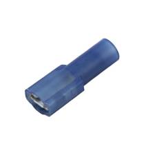
Fast-on female terminal
You can source these terminals from companies like Del City or Waytek Wire. Make sure that you are getting the right width of terminal. You also have to make sure that the terminal is the correct size for the gauge of wire. Our POWERCELL outputs use 14-AWG wire. Terminals to mate with 14-16 Gauge wire are usually blue. Pink or Red terminals are usually for 18-22 Gauge wire. We recommend using these insulated crimp connectors. You can use un-insulated terminals but we suggest applying heat-shrink tubing over the terminal to insulate the joint. You do not want to risk the terminal connected to the POWERCELL output accidentally touching the chassis.
Also, make sure that you are using the correct tool to make this crimp. As noted in other blog posts, you want to stay away from Radio Shack and Home Depot for car wiring. This includes for tools. Also, don’t just use a pair of pliers to crimp these terminals. A good crimp tool is an important investment and will save you problems down the road. This link will take you to a good quality crimp tool for these types of connectors.
The other of the two terminals on the horn needs to go to ground. There is no polarity on a horn so you can connect the POWERCELL output and the ground wire to either of the two terminals. Use the same Quick-Disconnect connector that you did for the POWERCELL output to connect the ground. Remember that the size of the ground wire should be the same as the size of the wire feeding the horn. That is good practice for any electrical connection. On the other side of the ground wire, crimp on a ring terminal and use a bolt to attach this to the chassis. Make sure that you have a good, metal-to-metal connection from your ground wire ring terminal to the chassis. You must remove all dirt, rust, paint, powder coating, oil and grease from the connection.
The example that we used above was for a two-terminal horn. You connected the POWERCELL output to one of the terminals on the horn. The other connected to ground. There are some horns that only have a single terminal on them. That terminal connects to the POWERCELL output. The horn grounds to the chassis through its mounting bracket. The same rules for grounding apply. You must have a clean metal-to-metal connection between the horn bracket and the chassis.
That’s it for this one. We’ll talk about wiring the MASTERCELL input wires in upcoming posts. If you have questions or comments about this post or any of the other steps in wiring this 1967 Mustang, please click on this link to contact our team.