Wiring the Holley Terminator EFI with the IPM1 Kit
Our Infinitybox system can power any ignition and fuel injection system out there. This post covers how to wire the Holley Terminator EFI system with our new IPM1 Kit featuring the MASTERCELL NGX. The wiring approach covered here also applies to the Holley Terminator X and Terminator X MAX systems. We will cover the differences between these systems below. If you have one of our Legacy 20-Circuit Kits, click here to get to the wiring details for that system.
We have blogged before about the Dominator and given detailed instructions on how to wire that system with our 20-Circuit Kit. You can see that here.
Table of Contents
- Overview
- Before You Start
- Connection Summary
- Wiring the Ignition Power
- Wiring the Fuel Pump Trigger
- Wiring the Cooling Fan Trigger
- How It All Works Together
- Terminator X and Terminator X MAX
- Legacy 20-Circuit Kit vs. IPM1 Kit
- Questions
Overview
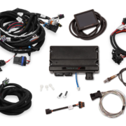
Holley makes several versions of the Terminator EFI system. The original Terminator EFI is a self-learning throttle body injection system. The Terminator X is a multi-port fuel injection system designed for LS and LT engine swaps. The Terminator X MAX adds drive-by-wire throttle body control to the Terminator X platform. All three systems use the same types of trigger signals for the fuel pump and cooling fans. That means the wiring approach with your Infinitybox IPM1 Kit is the same across the entire Terminator family.
Your Infinitybox IPM1 Kit is going to provide the ignition power to the Holley ECU. It is also going to take the fuel pump trigger signal from their ECU and the cooling fan trigger. These two triggers will go to the MASTERCELL NGX which will send signals to the POWERCELL in the front of the car for the cooling fan and the POWERCELL in the rear of the car for the fuel pump. This eliminates the need to add external relays because they are switched from inside the POWERCELLs. This also eliminates the need to run high-current wiring from the Holley Terminator EFI system to the front and back of the car. Those signals are sent through our CAN cable.
Before You Start
Before we go any farther, it is very important that you completely read and fully understand the manual that came with your Holley system. There are many different parts of properly installing these systems. The wiring is just one step. Here are links to the Holley manuals:
Once you have read and understand their manual, you must make all of the constant power and ground connections necessary for their system to work. There are multiple constant power feeds that must be wired directly to the battery and multiple ground connections. You must also wire in all of the other connections including the coil, tach, O2 sensors and others. Their manual will cover these details.
Connection Summary
Here are the points where your IPM1 Kit will connect to the Holley Terminator EFI system. These same connection points apply to the Terminator X and Terminator X MAX:
- The ignition output on your POWERCELL will supply the key-on power to their system.
- Their system will trigger the fuel pump output on your rear POWERCELL through the MASTERCELL NGX.
- Their system will trigger the cooling fan output on your front POWERCELL through the MASTERCELL NGX.
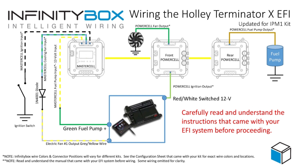
Wiring diagram showing the connections between the Holley Terminator EFI and the Infinitybox IPM1 Kit with the MASTERCELL NGX. This diagram also applies to the Holley Terminator X and Terminator X MAX systems.
You can download a PDF version of this wiring diagram by clicking on this link.
Wiring the Ignition Power
Let’s start with the key-on ignition power. This connection is the same across the original Terminator, the Terminator X and the Terminator X MAX. Check your configuration sheet and find the ignition output wire. In most cases, this is the light-green wire on the front POWERCELL. System configurations may vary so check the configuration sheet that came with your kit. The POWERCELL ignition output wire is going to connect to the red wire with the white stripe in the Holley ECU harness.
Wiring the Fuel Pump Trigger
The following section covers the fuel pump wiring for the original Holley Terminator EFI. If you have a Terminator X or Terminator X MAX, skip to the Terminator X section below for the details specific to your system.
Next, you need to connect the fuel pump trigger. In the ECU harness, there is a green fuel pump wire. This wire supplies 12-volts to drive a pump directly or to drive a relay coil.
The MASTERCELL NGX in the IPM1 Kit has both ground-switched and high-side switched inputs. The high-side switched inputs accept a 12-volt signal directly. This means you can connect the green fuel pump wire from the Holley Terminator harness directly to a high-side input on the MASTERCELL NGX. There is no need for an inVERT Mini or an external relay to flip this signal. This is one of the key advantages of the MASTERCELL NGX over our legacy MASTERCELL.
Check the configuration sheet that came with your kit. Find the MASTERCELL NGX input for your fuel pump. Confirm the wire color on your configuration sheet as different systems may have different wire colors.
There are several advantages of using the Infinitybox system to control the fuel pump directly from the Holley Terminator harness. First, we can disable the fuel pump as a security measure if you have our inLINK Radio upgrade. More importantly, having the Infinitybox system control the fuel pump means that you have to run less wire in the car. The MASTERCELL NGX is located close to the EFI system. The rear POWERCELL is mounted near the fuel pump in the tank. There is no extra fuel pump wiring required to make it work.
Wiring the Cooling Fan Trigger
The following section covers the cooling fan wiring for the original Holley Terminator EFI. If you have a Terminator X or Terminator X MAX, skip to the Terminator X section below for the details specific to your system.
Lastly, you need to wire the cooling fan trigger from the Holley Terminator EFI system to your MASTERCELL NGX. The gray wire with the black stripe in the Holley harness is the cooling fan trigger. This is a ground-switched signal so it can connect directly to a ground-switched input on the MASTERCELL NGX.
We recommend installing a 1N4001 diode in series between the MASTERCELL NGX input and the cooling fan trigger on the Holley harness. This diode acts as a one-way valve for the electrical signal. It protects the MASTERCELL NGX input from any voltage surges or back-feeds that could come from the ECU. You can get a 1N4001 diode from any electronics supplier.
Please note that the orientation of the diode is very important. The anode side of the diode connects toward the MASTERCELL NGX and the cathode side connects toward the Holley ECU. The cathode is the side of the diode with the stripe. The stripe on the diode should be on the ECU side of the connection, facing away from the MASTERCELL NGX. Check the wiring diagram above for the correct orientation.
There are several advantages to using the Infinitybox system to control the cooling fan directly off of the Holley Terminator harness. First, you do not need to add a relay. That is built into the POWERCELL. Second, our cooling fan outputs are set to soft-start the motor. Click here to learn more about the benefits of soft-starting.
How It All Works Together
When you turn the key, the front POWERCELL is going to apply battery power to the ignition input on the Holley Terminator EFI system. When the Terminator wants the fuel pump to turn on, it will send a 12-volt signal to the high-side input on the MASTERCELL NGX. The MASTERCELL NGX will then tell the rear POWERCELL to turn on the fuel pump. When the Terminator wants to turn the cooling fan on, it will send a ground signal to the MASTERCELL NGX. The MASTERCELL NGX will tell the front POWERCELL to turn on the cooling fan.
Terminator X and Terminator X MAX
Holley also makes the Terminator X and the Terminator X MAX. The Terminator X is a multi-port fuel injection (MPFI) system designed for LS and LT engine swaps. The Terminator X MAX adds drive-by-wire throttle body control. Both of these systems connect to the Infinitybox IPM1 Kit using the same wiring approach described above.
Fuel Pump
The Terminator X and Terminator X MAX have a green fuel pump wire that supplies 12-volts. This is the same type of signal as the original Terminator. Connect this green wire directly to a high-side input on the MASTERCELL NGX. There is no need for an inVERT Mini or an external relay. Please note that the Holley manual states that this green wire can power a fuel pump directly if it draws less than 15 amps. When you are using our Infinitybox system, you are not powering the pump from this wire. You are using it as a trigger signal to the MASTERCELL NGX. The rear POWERCELL will supply the power to run the fuel pump.
The Terminator X also has a separate fuel pump control output on Pin C5 of the I/O connector. This is a dark-blue wire that provides a low-current ground signal. If you prefer to use this output instead of the green wire, you can connect it to a ground-switched input on the MASTERCELL NGX with a 1N4001 diode for protection. Either approach will work. Consult the manual that came with your Terminator X or Terminator X MAX for the details on these wires and their connector locations.
Cooling Fans
The Terminator X and Terminator X MAX have dedicated cooling fan outputs on their 8-pin I/O connector. These are ground-switched signals that trigger external relays. Since these are ground signals, they connect directly to ground-switched inputs on the MASTERCELL NGX. Install a 1N4001 diode in series for protection, just like the original Terminator. The orientation of the diode is the same. The stripe on the diode faces away from the MASTERCELL NGX, toward the ECU.
The Terminator X and Terminator X MAX support two separate cooling fan outputs from the I/O connector. If you have a dual-fan setup, you can connect both fan outputs to separate inputs on the MASTERCELL NGX and control them independently. This gives you the ability to stage your cooling fans based on the temperature thresholds that you set in the Holley software.
Ignition Power
The key-on ignition power connection is the same for the Terminator X and Terminator X MAX. Connect your POWERCELL ignition output to the red wire with the white stripe in the Holley harness. Always check your Infinitybox configuration sheet and the Holley manual to confirm wire colors for your specific system.
Legacy 20-Circuit Kit vs. IPM1 Kit
If you have one of our Legacy 20-Circuit Kits, the wiring for the Holley Terminator EFI is slightly different. The legacy MASTERCELL only has ground-switched inputs. That means you need an inVERT Mini or an external relay to convert the 12-volt fuel pump trigger from the Holley harness to a ground signal for the MASTERCELL input. Click here to get to the Legacy 20-Circuit Kit wiring details for the Holley Terminator EFI.
The MASTERCELL NGX in the IPM1 Kit eliminates the need for that extra component. Its high-side switched inputs accept 12-volt signals directly. The IPM1 Kit also includes built-in low-current indicator outputs on the MASTERCELL NGX for your dash indicators and the system is fully programmable and configurable by the customer using our inCODE NGX software.
Questions
If you have questions about this wiring diagram or wiring anything else with our Infinitybox system, click on this link to contact a member of our team.

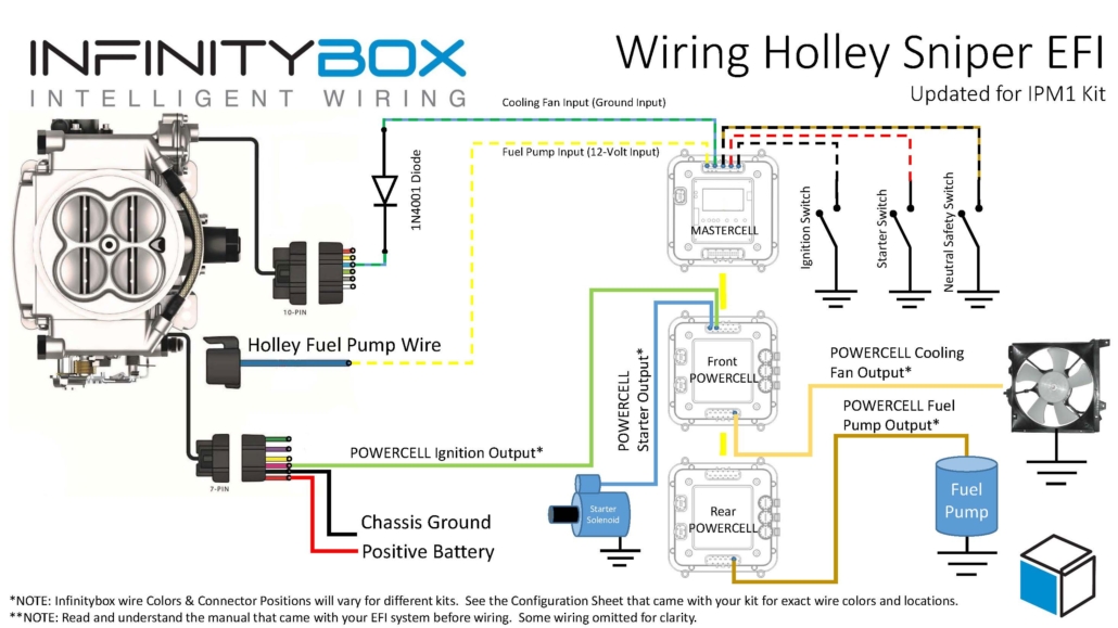
 Image used courtesy of Holley Performance Products, Inc.

 Copyright Infinitybox, LLC 2021. All Rights Reserved.

 Copyright Infinitybox, LLC 2021. All Rights Reserved.