Posts

Soldering Components In-Line

Okay… we do our best to not take things for granted.  In all of our blog posts, we always try to give you as much fundamental information on the material that we are presenting.  Every once in a while, we get called out by our customers for not explaining something thoroughly.  This post is intended to fix this.  In a lot of our blog posts and wiring diagrams, we show components installed in-line with a MASTERCELL input or a connection to ground.

In our last blog post, we showed wiring a 10K pull up resistor on a brake-pedal switch.  You can see that blog post here.  In other blog posts, we’ve shown wiring diodes in-line between a trigger on an ECU and a MASTERCELL input.  You can click here to see a recent example blog post.  Someone just asked us an obvious question on our last blog post.  “How do I install the diode or the resistor in the wire”.  We’ll show you how.  This isn’t the only way to do this but it is our recommended way to do this.

There are three important factors to consider when installing an in-line component in a wire.  First, you need to have good electrical connection.  Second, you need to protect it mechanically.  Lastly, you need to protect the joint from the environment.

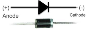
These steps will show you how to solder an axial, leaded component in-line with a wire.  A leaded part has metal terminals coming off its ends.  An axial part has the leads running along the axis of the component.  This picture shows you a good example of an axial, leaded diode.

Example of a simple diode

Example of a simple diode


Speaking of diodes, remember that they have a direction to them.  Check our wiring diagram for proper orientation of the diodes.  Resistors do not have a direction so you can install them either way in your wiring harness.

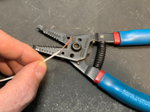
The first step is to strip back the insulation on the wire you’re connecting to your component.

Next, you want to twist the strands of the copper wire together.  This will make the next steps easier by keeping the strands together.

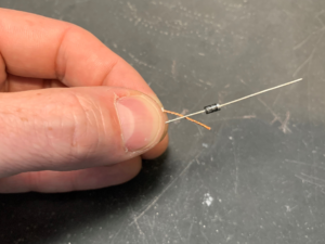
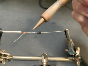
Next, twist the strands of the wire with the lead coming from your component.  We recommend leaving some length of the lead at the end as shown in this picture.

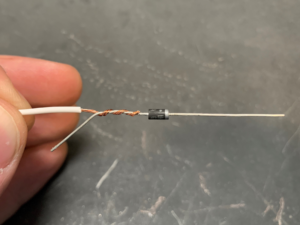
The next step is to make a good electrical connection between your wire and the lead on your component.  This needs to be soldered.  A good soldering iron and electrical solder will make this job easy.  You want to make sure that you are heating the joint thoroughly and that the solder is flowing between the copper wire and the lead on your component.  When you’re finished, the joint should be shiny.  If your joint looks grey or dull, you need to apply more heat and solder.  We also recommend keeping the solder on the joint between the copper wire and the lead on the component.  You do not want the solder to wick up the copper wire under the insulation.  This will make the joint inflexible and it could fail over time.

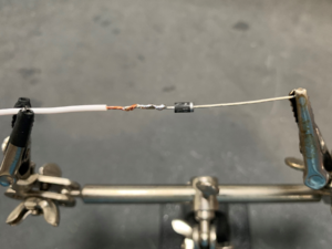
Once you have the joint soldered, clip off the extra length of lead on the component.

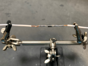
Repeat this process for the other side of your component.

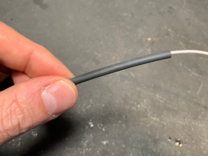
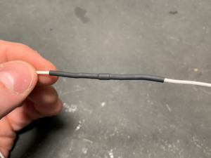
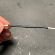
Now you have a good electrical connection between your wires and your component.  The next step is to protect the component mechanically and from the environment.  To do this, we recommend a good quality heat shrink tubing.  Heat shrink tubing does what its name suggests.  It shrinks around a joint when you heat it.  Cut a length of heat shrink tubing that is slightly larger in diameter than the component that you soldered in line.  You want the length of this tubing to extend past the exposed area of your joint by about 1/2″ on both sides.

Use a hot air gun to heat the tubing and shrink it over the component and the joints.  We know that a lot of guys like to use lighters or torches to do this but we really recommend a hot air gun for better control and safety.

The heat shrink tubing is going to do two important things.  First, it is going to mechanically strain relieve your joints.  This will keep the joints from failing due to vibration of mechanical stress.  We recommend that you zip tie these components in the harness to minimize any bending or movement as an added precaution.  Secondly, the heat shrink tubing is going to protect the joints from exposure to moisture, dirt and other chemicals in your car.

Soldering in-line components in your harness is a simple thing to do.  If you have any additional questions about this, please click on this link to contact our technical support team.



Wiring Switches in Parallel

Our Infinitybox system is the most powerful and flexible wiring harness available in the market. Our MASTERCELL inputs are flexible and adaptable for practically any application. A customer just asked this question and we thought that it was a great way to show off the flexibility of the MASTERCELL inputs. The customer is wiring the power window switches in his car. He wanted to know if there was a way to wire a parallel switch that would control all 4 windows at the same time. The answer is “yes” and this blog post will show you how to do it.

Our MASTERCELL inputs work by getting connected to ground. This link will take you to an older blog post that goes through the details of how the inputs work and how to connect a switch to them. Since the inputs work by a ground trigger, this gives you a lot of flexibility with your switches.

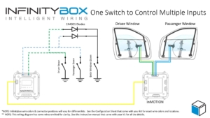
This picture shows you how to wire in a parallel switch to control multiple inputs simultaneously.

Picture of a wiring diagram showing how to wire two Infinitybox MASTERCELL inputs in parallel

Picture of a wiring diagram showing how to wire two Infinitybox MASTERCELL inputs in parallel

In this example, we’re showing two switches that control the driver’s and passenger’s windows. For the sake of clarity, we’re only showing the front windows and we’re only showing the down action. These switches are labeled Driver Down and Passenger Down in the wiring diagram. You are going to follow the wire colors from your configuration sheet to wire the switches and the power wires that go to the window regulator motors.

To wire in the parallel “master” switch, you are going to connect the MASTERCELL inputs for the Driver’s and Passenger’s switch together and bring them to the parallel switch. The important thing here is that you need to put a diode on each of the wires from the Driver’s and Passenger’s switch. These diodes are electrical check valves. They only let current flow in one direction. They block the flow of current in the other direction. Without these diodes, both the MASTERCELL inputs would be connected together at the parallel switch. They would both turn on with either switch. The diodes electrically isolate the two MASTERCELL inputs so they are operate independently from the individual switches but work together from the parallel switch.

You can source these diodes anywhere. We recommend a 1N4001 diode. These can be purchased easily from Amazon or other on-line retailers. The orientation of the diodes critical. This will not work correctly if they are installed backwards. Note the orientation of the diode symbol in the wiring diagram above. The line on the diode symbol corresponds to the silver line on the case of the diode. Look at the picture below.

Example of a simple diode

Example of a simple diode

We only show the down action for the power windows in this diagram. We also only show 2 window switches. You can join all 4 inputs together through diodes if you want to control your front and rear windows from a single parallel switch. You can also repeat this for the up action of your power windows.

This same approach can be used for other switches like your lighting. We posted a wiring diagram a while ago showing you how to wire your head lights and parking lights from a single switch using a similar arrangement. You can view that blog post by clicking this link.

Click on this link to download a PDF version of this wiring diagram.

Click on this link to contact our technical support team with any additional questions about wiring your car or truck with our Infinitybox system.


Switch Terminals

We’re progressing through the different switches that need to get wired to the MASTERCELL in our customer’s 1967 Mustang.  They are wiring their car with our 20-Circuit Kit.  The last post covered the brake pedal switch, which is one of the easiest.  In this post, we’re going to talk about how you figure out which switch terminals you need to connect to your MASTERCELL inputs.

Some switches are really easy, the brake pedal switch is an example.  Others, we have created wiring diagrams for you to use.  Our Resources section of our website has a long list of turn signal switches, ignition switches and headlight switches from different makes of car.  You can find these under the Installation Guides section at this link.  

There are some switches that are unique to a model year or are unique to a specific car.  We may not have a wiring diagram assembled for your specific switch.  It is usually pretty simple to figure out how to connect these switches to your MASTERCELL inputs.  We’ll talk about the basics in this blog post.

Remember how a MASTERCELL input works.  The MASTERCELL input gets triggered by getting connected to ground through the switch.  In the case of the brake switch from our last post, that one was easy.  One of the switch terminals connected to the MASTERCELL input.  The other of the switch terminals connected to ground.

There are a few simple steps to follow to figure out which switch terminals you need to connect to for a new switch.

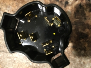
The first step is to find out where power came into the switch originally.  Let’s use this switch as an example.  One of our customers is wiring a 1972 Chevy truck with our 20-Circuit Kit.  He sent us this picture of his ignition switch.

Picture of a typical Chevy truck ignition switch.

Picture of a typical Chevy truck ignition switch.

He didn’t know how to connect his MASTERCELL inputs to the switch terminals on the switch. If you look at the terminals on the switch, there are two labeled BAT.  These are in the lower right corner of the picture.  In most cases, BAT is where the battery originally connected to the switch.  Ignition switches usually have two separate battery feeds: a dedicated one for the starter solenoid and one for the ignition feed.

You will also see that there is a terminal labeled IGN and one for SOL.  At a first glance, you can assume that these are for the ignition power and starter solenoid feeds.

You are looking for terminals that have continuity between them when the switch is on.  In the case of this ignition switch, you need to find the terminals that have continuity when the switch is in the run position for the ignition input.  You also have to find the pair that have continuity in the start position for the starter input.

If you can, search the internet to see if you can find wiring diagrams for that specific switch.  We’re always surprised to find that there is a forum or chat group for practically any type of car out there.  Someone has worked on that switch before you and they have posted some wiring diagrams.

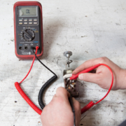
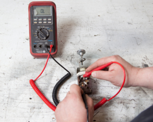
Once you have identified the terminals on the switch, get a multi-meter and check continuity between the terminals.  If you don’t already have one, a good multi-meter is a powerful tool to have in the shop.  The two most critical things that you have to measure would be voltage and resistance.  Here is a simple meter that you can source from Waytek Wire.  Here is an example of a meter from Del City.

Picture showing how to use a multimeter to check continuity between terminals on a headlight switch

Picture showing how to use a multimeter to check continuity between terminals on a headlight switch

To figure out our switch terminals, we want to measure continuity or resistance.  If a circuit has continuity, it should have low resistance between the terminals.  Low should be less than 1 Ohm.  Look for the resistance setting on your meter.  On most meters, this is represented by the Greek letter Omega that looks like this: Ω.

Represents electrical resistance

Represents electrical resistance

Some meters have an auto-range function that will internally adjust to select the right range to measure resistance.  Others have a dial to select the range.  You want to set the range of your resistance measurement to the lowest range. To measure resistance, it really doesn’t matter if you have the red or black leads from the meter touching the different terminals.

Touch the test leads from your meter to the terminals with the switch in the off position.  You should measure very high resistance or no change in resistance.  In the case of this 1972 Chevy ignition switch, we were measuring between each of the BAT terminals and the IGN terminal with the switch off.  We repeated this by measuring between each of the BAT terminals and the SOL terminal.  We measured a resistance in the mega-ohm range.  Some meters will show this as “OL” or “overload”.

We then turned the switch to the ON position and measured between the BAT terminals and the IGN terminal.  We found that we had about 0.4 Ohms of resistance between the inner BAT terminal and the IGN terminal when the switch was in the ON position.  In the case of this switch, we will connect the MASTERCELL ignition input wire to the IGN terminal and connect one of the ground wires from the MASTERCELL input harness to the inner BAT terminal.  When the switch is in the ON position, there is continuity between IGN and the inner BAT terminal.  This will ground the MASTERCELL input, which will turn on the Ignition output on the POWERCELL.

We repeated this for the SOL terminal.  We measured between SOL and both of the BAT terminals when the switch was in the START position.  We found that the outer BAT terminal was connected to the SOL terminal in the start position.  We will connect the MASTERCELL input wire for the starter to the SOL terminal and connect one of the MASTERCELL ground wires to the outer BAT terminal.  When the key is in the START position, there is continuity between the SOL terminal and the outer BAT terminal.  This will ground the MASTERCELL input for the starter, which will turn on the starter output on the POWERCELL.

Just as a sanity check, we went back and measured resistance between the IGN terminal and the inner BAT terminal when the switch was in the START position.  When the switch is in the START position, you must still have continuity between the IGN terminal and its ground connection so that the engine will start.  The IGN terminal has continuity to its ground connection when the key is in the start position.

Figuring out how to wire your switch to  your MASTERCELL inputs can be scary.  We’ve built a large of list of different switches over the years but the steps above will help you to figure out any switch in your car.  Click on this link to contact our team with questions.

Wiring the FAST EZ-EFI

Our Infinitybox wiring harness can be used to provide switch electrical power to just about anything in your car.  This post shows you what you need for wiring the FAST EZ-EFI system.

First, installing any fuel injection system is a process.  Familiarize yourself with the instructions for the EZ-EFI system.  You can download them at this link.

Wiring the EZ-EFI is pretty straight forward.  You are going to use the ignition output on your POWERCELL to supply the switched 12-volts for the EFI system.  The MASTERCELL and POWERCELL in your 20-circuit harness replace the need for the relays to control the fuel pump and the cooling fan.  Connect the wires in their harness per this diagram.

Picture of wiring diagram showing how to wire the FAST EZ-EFI fuel injection system with the Infinitybox system.

Picture of wiring diagram showing how to wire the FAST EZ-EFI fuel injection system with the Infinitybox system.

It is important that you install the diodes that are shown in the diagram.  Our recommendation is to use a 1N4001 diode.  You can purchase these easily on-line.  Please note that the orientation of the diode is important.

You can download a PDF of this wiring diagram by clicking this link.

Give our technical support team a call at (847) 232-1991 if you have questions about wiring the FAST EZ-EFI system.

Picture of the Limeworks TS1342 Turn Signal Switch

Wiring Turn Signals- Limeworks TS1342

We get a lot of questions about wiring turn signals.  Our MASTERCELL inputs are very flexible.  These let you connect practically any switch to the Infinitybox system.  We have other blog posts that show you how to wire GM-style steering columns to the Infinitybox MASTERCELL.  You can check that out here.  Flaming River columns and IDIDIT columns use the exact same connector so you can use the same instructions.

We got a call from a customer installing a TS1342 turn signal switch sold by Limeworks.  This is a very classy turn signal switch with a very retro look.  There are two versions:  one for a 1 1/2″ column and one for a 1 3/4″ column.  It also has a lit end that can be used as a turn signal indicator if you don’t have one on your dash.

The customer asked about how to wire the turn signal switch into his Infinitybox MASTERCELL.  It’s is such a good question, we created a new application note for it and posted it.

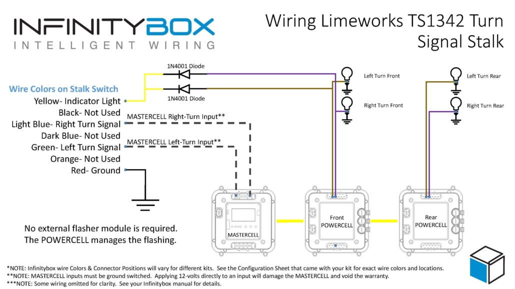
The wiring diagram that comes with the switch shows the need to use a 3-prong flasher module.  You need this if you’re connecting it to a traditional wiring harness.  If you’re connecting it to our Infinitybox system, you don’t need the flasher.  We build that into the system so no external flashers are required.   This diagram shows you how to connect the Limeworks TS1342 turn signal switch into the Infinitybox system.

Picture of wiring diagram showing how to wire the Limeworks TS1342 turn signal switch with the Infinitybox system.

Picture of wiring diagram showing how to wire the Limeworks TS1342 turn signal switch with the Infinitybox system.

The MASTERCELL inputs work by getting connected to ground.  This column switch was designed to supply battery voltage to a flasher, which fed the turn signal bulbs.  As we said above, we can eliminate the flasher.  To make it work with the MASTERCELL inputs, you simply ground the wire on the switch that was connected to the battery.  The two wires that connected to the left and right turn signals will connect to their respective inputs on the MASTERCELL.  That’s it.  When you push the switch to the left, you’re electrically connecting the former power wire to the left turn signal input.  Since the former power wire is grounded, the left turn signal input wire gets connected to ground.  The MASTERCELL sees this and tells the POWERCELLs to flash the left turn signal.  The same thing happens for the right turn signal.  The diagram shows you which wires on the switch need to connect to the MASTERCELL inputs.  Use the configuration sheet that came with your kit as a guide to identify the MASTERCELL wire colors.

The other thing that you’ll notice in our wiring diagram is that the brake pedal switch doesn’t get connected to the turn signal switch.  The original wiring diagram had that because the brake pedal jumpered the left and right turn signals together for the brake lights.  This is something that we manage within the MASTERCELL.  If your rear turn signals are also your brake lights, you simply use the MASTERCELL input that is assigned to the 1-filament brake lights and connect that to your brake pedal switch.

The last thing to talk about in this post is turn signal indicators.  Depending on your gauges, you can handle this a few different ways.  If you have turn signal indicators on your dash, we recommend splicing off the left and right turn signal outputs on the front POWERCELL and connect them to the indicators.  Most turn signal indicators draw very little current so you can run a light gauge wire, like 22-AWG from the POWERCELL outputs to the indicators.  If you’re using LED’s make sure that you’re paying attention to their polarity.  Also, check the voltage rating of your LED’s.  Most are rated to 5 volts or less.  You may have to add a resistor in series to limit the current flowing through the LED.  Give our tech guys a call if you have question here.

One of the cool things about the TS1342 is that it has an indicator light on the tip of the stalk.  It can flash when the turn signals are flashing.  To do this, you need to splice off the POWERCELL outputs for the left & right turn signals like I mentioned above.  Since there is only one light, you need to connect the outputs together.  However, you need to put diodes in the circuit to isolate the left turn signal from the right.  Without these diodes, the left turn signal would flash when the right was flashing and vice veat companies like www.digikey.com or www.mouser.com.  Or you can pick these up at a Radio Shack if they are still open where you are.  See the diagram for details on how to install these diodes.  Remember, the orientation of the diodes is critical.

You can download a PDF of this application note showing wiring turn signals using the Limeworks TS1342 turn signal switch.  If you have any questions about this, feel free to reach out to our technical support team at (847) 232-1991.  Or click on this link to contact our team directly.

Picture of the Honda S2000 Engine Start Button.

One-Button Start

A lot of our customers use our One-Button Start function.  This is standard in our 10 and 20-Circuit Harness Kits.

To start your engine, you have a few options when you wire your car with the Infinitybox.  You can use a traditional keyed ignition switch.  You pick our standard input wires for the ignition and starter and wire those to the switch.

Or you can use our One-Button Start function.  This involves taking one MASTERCELL input wire and connecting it to a momentary button.  That is all you need to manage your ignition and starter outputs.

When you press and release the button, the ignition output turns on.  When you press and release the button again, the ignition output turns off.  Pretty simple.  To start the engine, you simply press and hold the button.  The POWERCELL turns on the ignition, waits one second for the fuel pump to prime, then cranks the starter solenoid.  The starter will crank as long as you are pressing the button.  When the engine starts, you simply release the button and the starter will stop cranking.  The POWERCELL turns off the starter output but leaves the ignition output live so the engine will run.  To shut down the engine, you simply press and release the button again.

A lot of our customers use the Honda S2000 Start button.  This is a really popular button.  This link will take you to a wiring diagram showing how to use the Honda S2000 button with our one-button start.

You will note one thing about the way the Infinitybox One-Button Start works.  If you press and release the button to turn on the ignition, you have to press and release the button to turn the ignition off before you can press and hold it to crank the engine.  The personality that manages this function does this for a very important reason.  We don’t know if the engine is already running when you press the button.  Pressing and releasing the starter button forces the system to shut off the ignition output so that you cannot accidentally crank the starter with the engine running.

This function is another great example of how Infinitybox can help you to simplify the electrical system in your car.  You can certainly get a starter function similar to ours but it requires a separate box to manage the function.  With Infinitybox, you can eliminate the need for extra control modules to have to connect into your wiring harness.

Click this link to contact our team with any questions about using our one-button start feature.