
 Copyright 2026 Infinitybox, LLC. All Rights Reserved.
 Install inLINK NGX
The Infinitybox inLINK NGX Interface Kit puts three features on one small circuit board that lives inside your MASTERCELL NGX: Remote Keyless Entry, Passive Keyless Entry and the Infinitybox inTOUCH touch screen interface. Use one of them or use all three.
The kit comes with two 4-button key fobs. Those four buttons give you eight functions with a range up to 100 feet. Lock and unlock your doors, arm and disarm your security, run your lights or pop your trunk. Pair your phone to inLINK NGX over Bluetooth and your car unlocks and disarms as you walk up to it, then locks and arms as you walk away. Connect to the secure Wi-Fi network that inLINK NGX broadcasts and you get a full set of touch screens for your lights, windows, locks, heat and A/C, ignition, starter and anything else running through your IPM1 Kit or inMOTION NGX. No Internet connection and no data plan.
Order inLINK NGX with your IPM1 Kit and we install it at the factory. Add it later and you install it yourself. This post covers how to install it yourself. The board is plug-and-play and there is nothing to program. Your MASTERCELL NGX finds it on its own.
Please note that this blog post covers the MASTERCELL NGX in our Next Generation IPM1 Kit. The inLINK NGX board is specific to our Next Generation hardware and only installs into the MASTERCELL NGX. It will not work in our Legacy 3-Cell Kit, Legacy 20-Circuit Kit or Legacy 10-Circuit Kit.
Before You Start
Work on a clean bench with good light. You will have the MASTERCELL NGX circuit board out of its housing, so ground yourself before you touch it and handle it by the edges. Static kills electronics.
If your MASTERCELL NGX is already mounted in your car, disconnect your battery before you unplug anything.
You need a Phillips screwdriver and a small screwdriver or pick.
Your inLINK NGX kit includes the receiver board, two screws, two plastic spacers, two key fobs and an installation guide. Both antennas are already connected to the board.
Step 1: Disconnect the MASTERCELL NGX
You need to get to the back of your MASTERCELL NGX. If it is mounted in your car, take it out. Unplug the two input connectors and the CAN connector. Press the lock on each connector and pull it straight up.
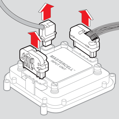
Unplug the two input connectors and the CAN connector from your MASTERCELL NGX.
Step 2: Remove the Screws from the Back Cover
Set the MASTERCELL NGX on your bench with the inSIGHT screen facing down and the back cover facing up. Keep it in this position for the next several steps. If you turn it over, the buttons fall out.
Eight screws hold the back cover to the housing. Back all eight out with a Phillips screwdriver and put them somewhere safe. You need them again at the end.
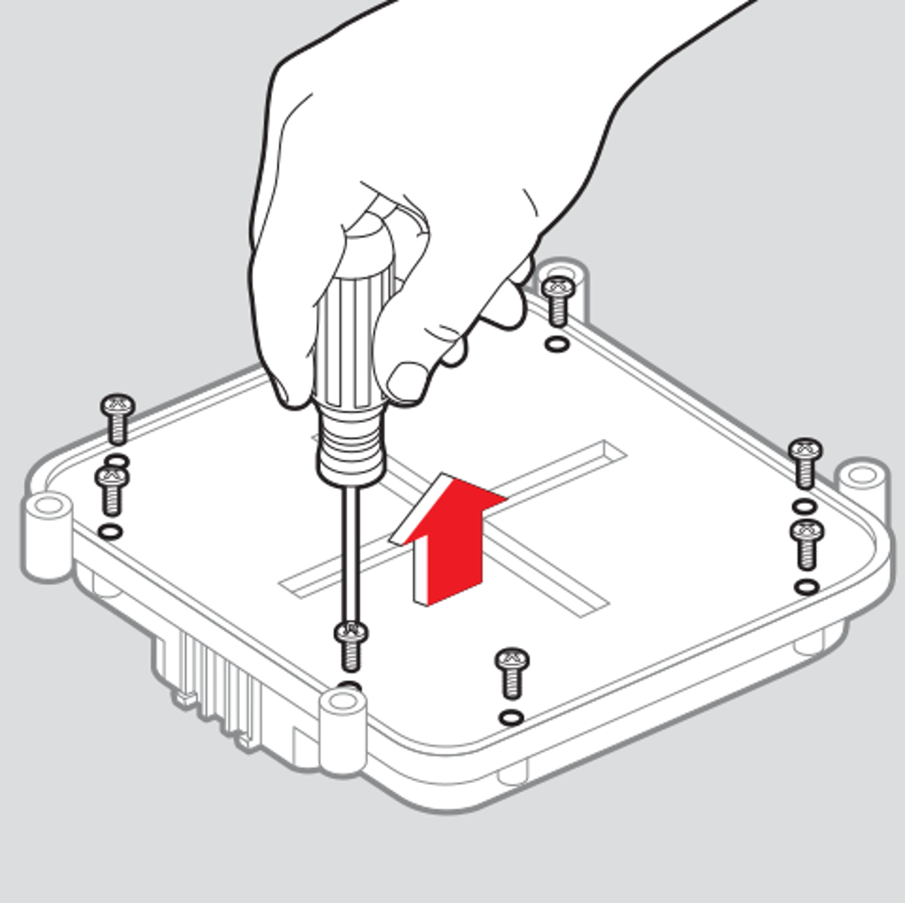
Back all eight screws out of the back cover and put them somewhere safe.
Step 3: Remove the Back Cover
The back cover does not lift straight off. Reach underneath and push up on the input connector pins with your fingers. That pushes the back cover away from the housing.
Lift the back cover off. The circuit board comes with it. Set the housing down and leave it face down.
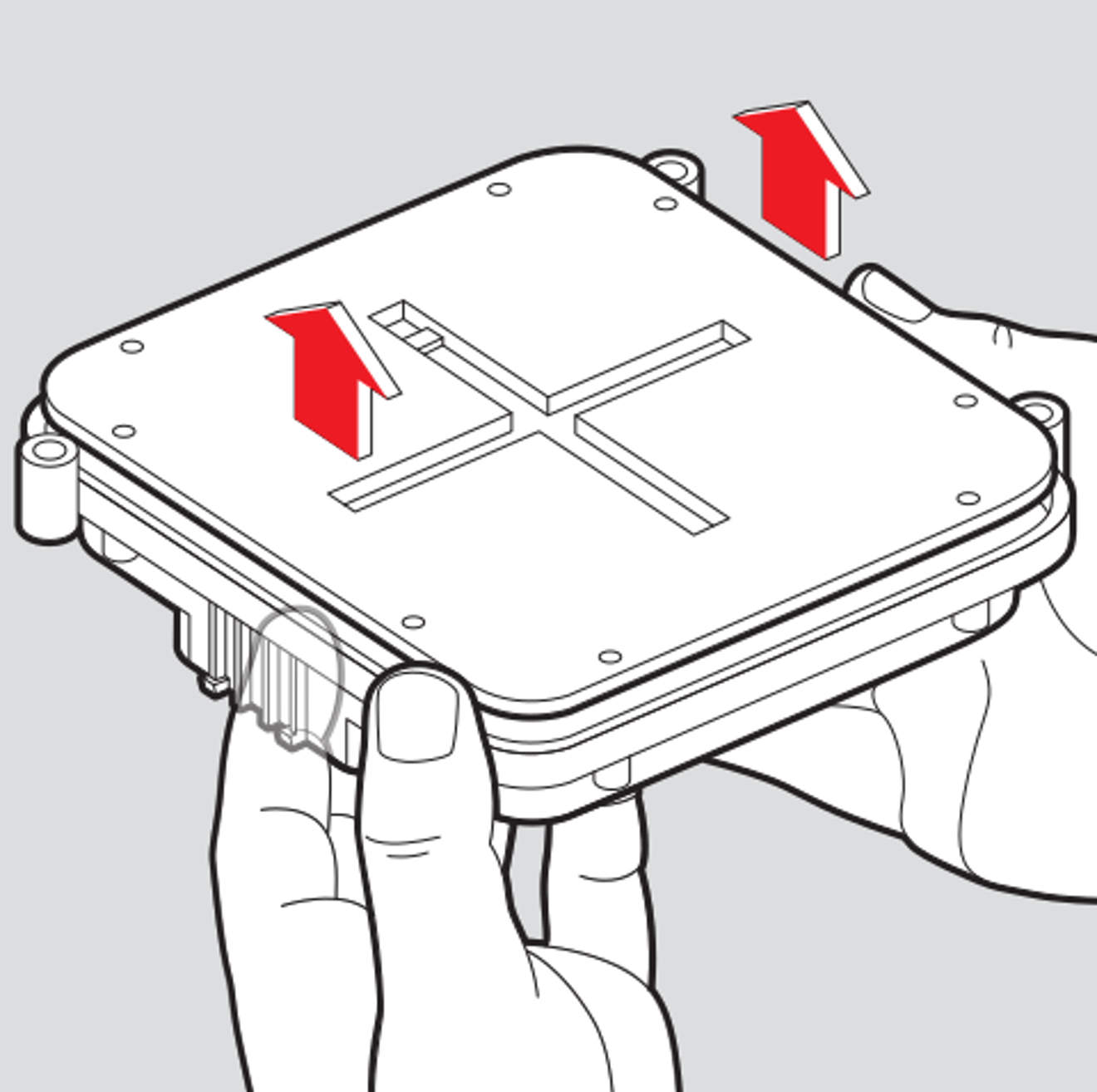
Push up on the input connector pins to lift the back cover off the housing.
Step 4: Set the Spacers on the Board
Find the two holes in the MASTERCELL NGX circuit board below the inSIGHT screen. Set a plastic spacer over each hole.
The spacers do two jobs. They hold the inLINK NGX board off the MASTERCELL NGX board, and they line it up so it plugs into the socket correctly. Leave them sitting in place and move to the next step.
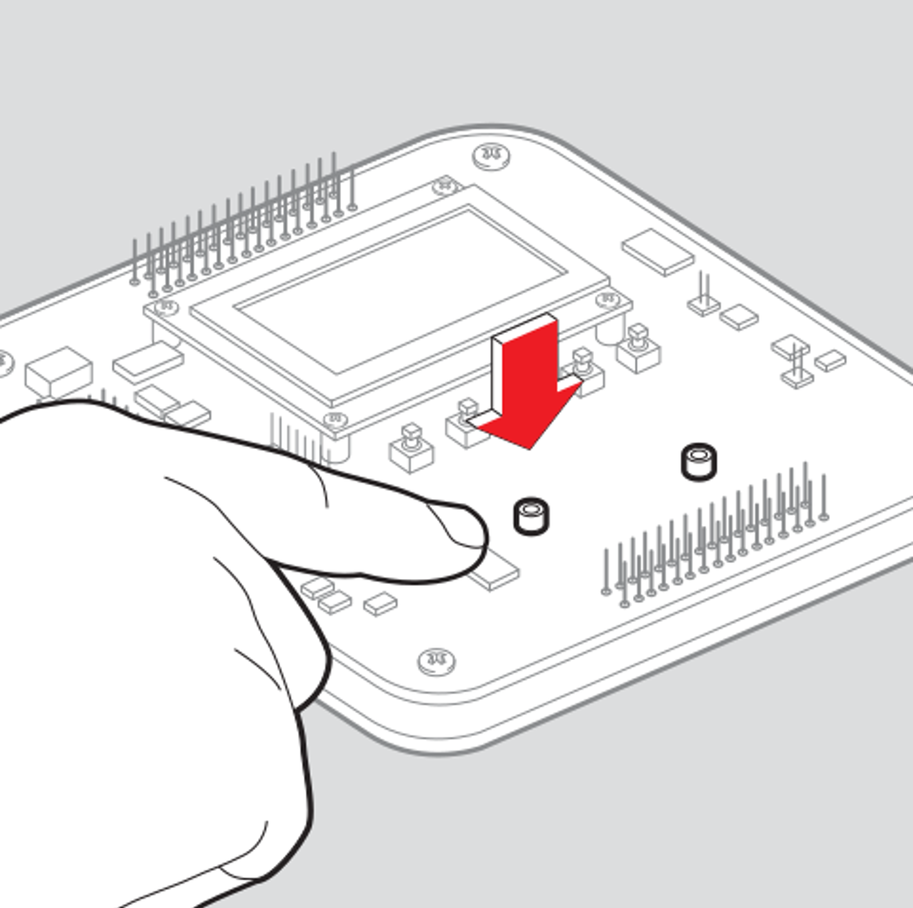
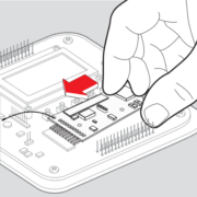
Set a plastic spacer over each of the two holes below the inSIGHT screen.
Step 5: Plug in the inLINK NGX Board
Hold the spacers where they are. Line the connector on the bottom of the inLINK NGX board up with the pin header on the MASTERCELL NGX board.
The header has one more pin than the connector. Line them up so the leftover pin is the one furthest from the inSIGHT screen. Every other pin on the header goes into the connector.
Press the inLINK NGX board down until the connector is fully seated on the header. Check that both spacers are still lined up with their holes. If one has shifted, move it back with a small screwdriver or a pick.
Route the thin wire antenna under the inSIGHT screen. That is the 433 MHz antenna for your key fobs.
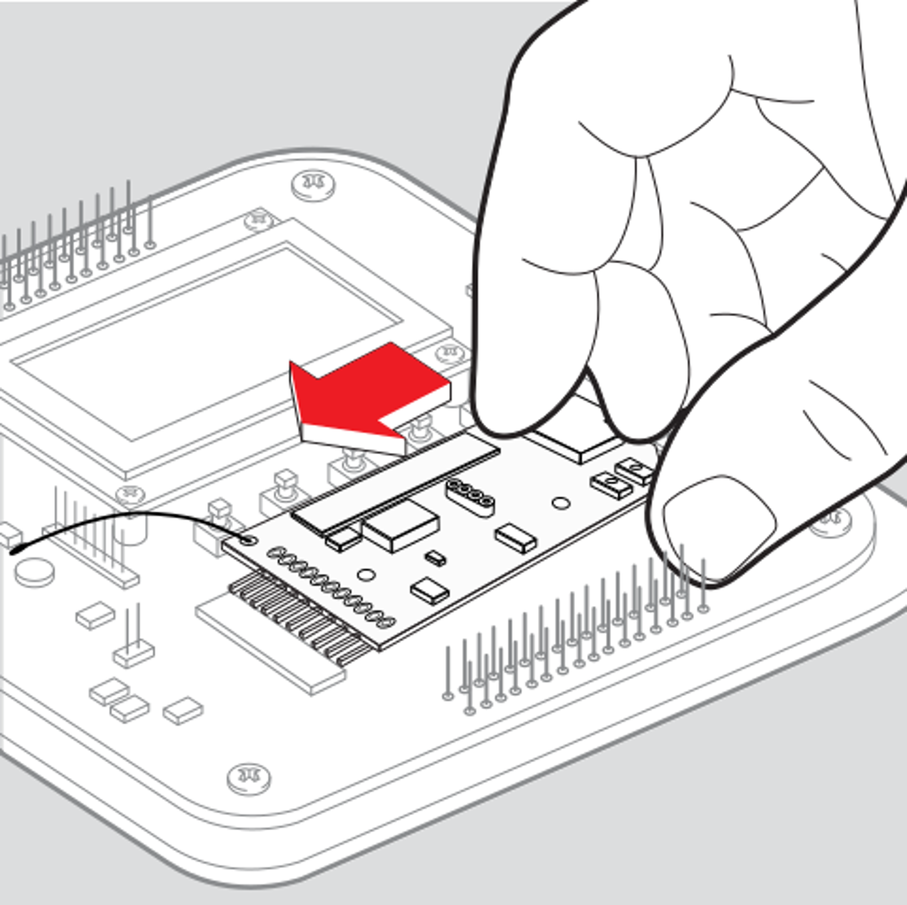
Seat the inLINK NGX board on the header, then route the 433 MHz wire antenna under the inSIGHT screen.
Step 6: Screw Down the inLINK NGX Board
Run the two 4-40 screws through the inLINK NGX board and into the spacers. Snug them down until the board is solid.
Important: Do not over-tighten these screws. You can crack the circuit board.
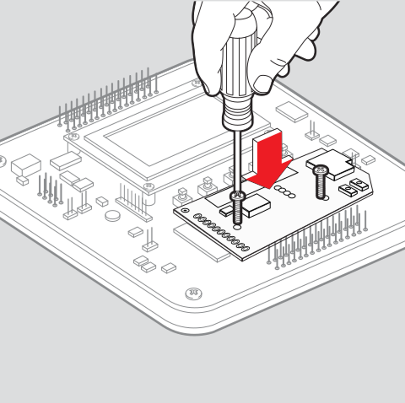
Run the two 4-40 screws through the board and into the spacers. Do not over-tighten.
Step 7: Mount the Wi-Fi Antenna
Pick up the front housing you set aside in Step 3 and keep it face down.
The flat rectangular antenna on the black wire is the Wi-Fi antenna. It mounts inside the front housing, in the open area next to the inSIGHT screen opening. The double sided tape is already on the back of it. Peel the backing off, set the antenna in place and press it down.
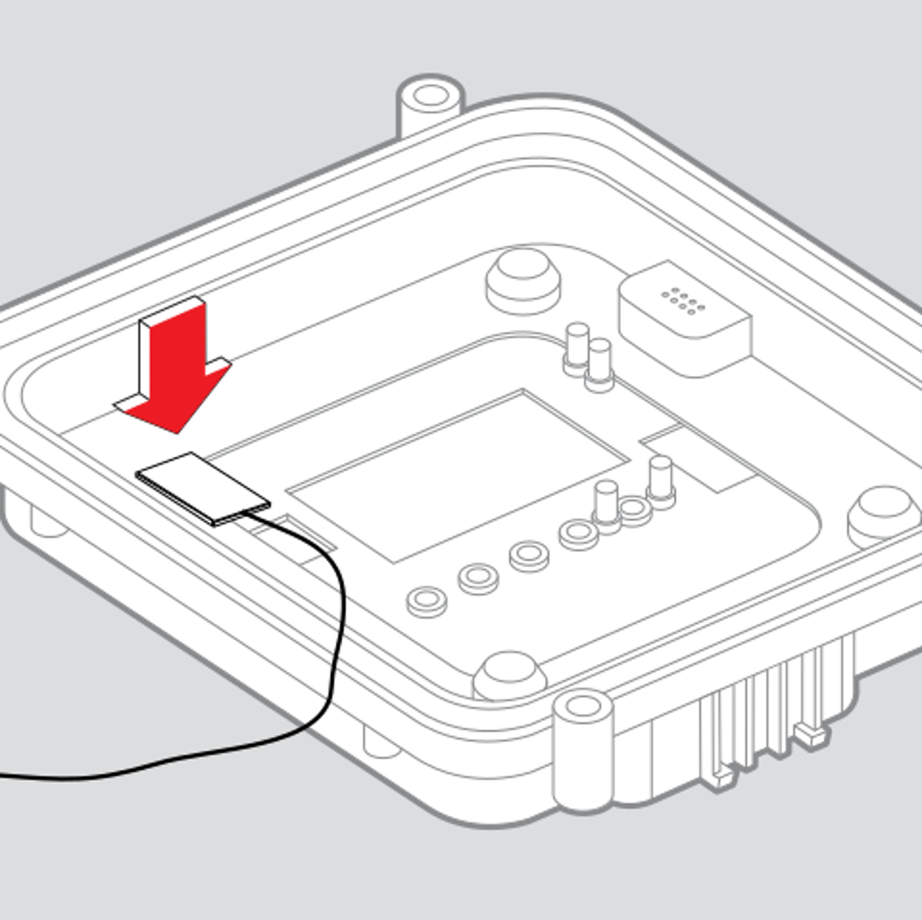
Peel the backing and press the Wi-Fi antenna into the front housing next to the screen opening.
Step 8: Put the MASTERCELL NGX Back Together
Keep the housing face down through this whole step. Turn it over and the buttons fall out.
Check that both antennas are still connected to the inLINK NGX board. The Wi-Fi antenna wire needs to sit flat so it does not get pinched.
Bring the circuit board and back cover down onto the housing. Line the input pins up with their holes. Press down evenly until every pin comes through and the back cover seats against the housing. It should sit flat with no gap.
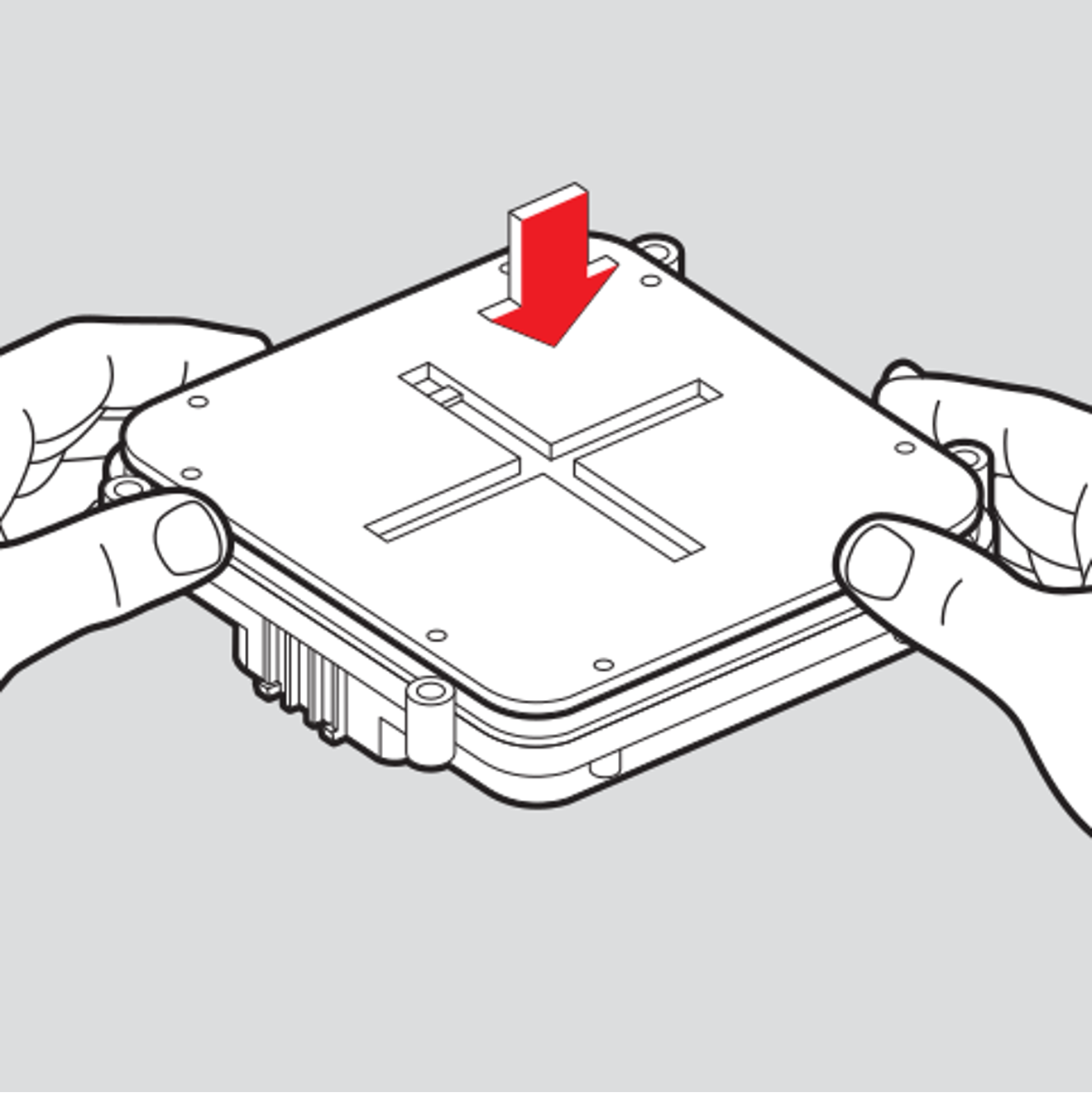
Press the board and back cover down until every input pin comes through and the cover sits flat.
Step 9: Reinstall the Back Cover Screws
Run all eight screws back into the back cover and snug them down.
Important: Do not over-tighten these screws. You can strip the plastic.
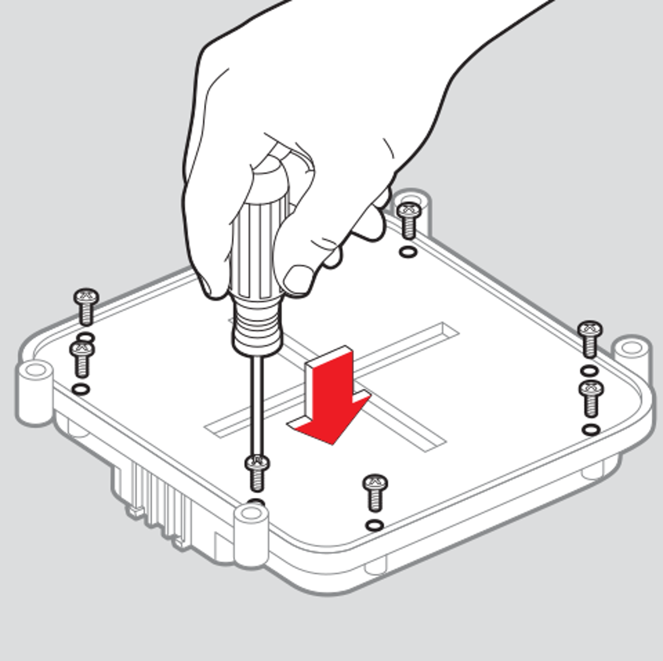
Run all eight screws back into the back cover. Do not over-tighten.
Step 10: Reconnect the MASTERCELL NGX
Plug the two input connectors and the CAN connector back in. Push each one down until it locks. Check your configuration sheet to confirm each connector goes back where it came from. Your configuration sheet is the single point of truth for your system.
Mount the MASTERCELL NGX back in your car and reconnect your battery.
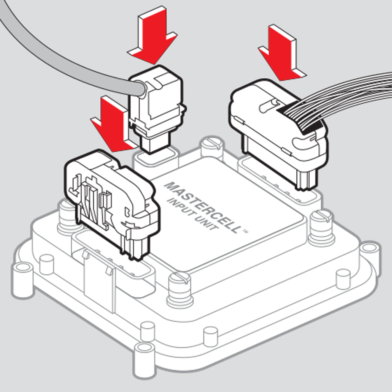
Plug the two input connectors and the CAN connector back in until each one locks.
Confirm inLINK NGX Is Installed
Power your system up and check the System Inventory screen on your MASTERCELL NGX. inLINK NGX shows up in the list. That is your confirmation that the MASTERCELL NGX found the board. Click here to learn how to read the System Inventory screen.
There is nothing to program. Your key fobs are ready to pair and your inTOUCH screens are ready to connect.
Questions about installing inLINK NGX? Call our team at (847) 232-1991 or fill out our contact form at this link. We are happy to help.
 Copyright 2026 Infinitybox, LLC. All Rights Reserved.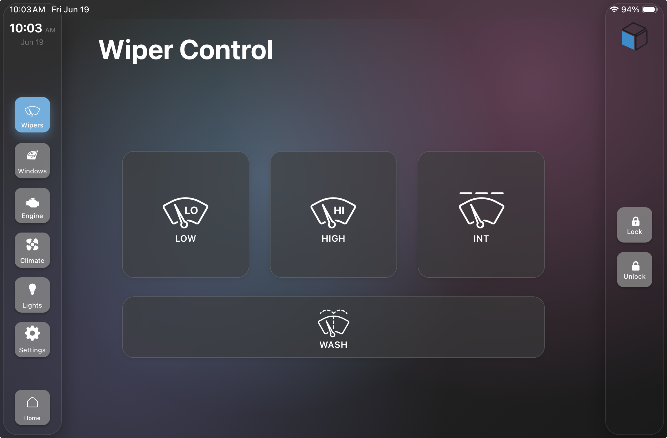
 Copyright Infinitybox, LLC 2021. All Rights Reserved.