

How to Configure inMOTION NGX Door Modules with the MASTERCELL NGX
Table of Contents
- What Changed
- Before You Start
- inMOTION NGX Door Positions
- Step-by-Step: Configure inMOTION NGX
- Troubleshooting
- Download the Full Manual
- Questions?
What Changed
If you purchased your inMOTION NGX modules before April 1st, 2026, they came preconfigured for a specific door position. You ordered a Driver Front module, a Passenger Front module and so on. Each one was programmed before it shipped.
Starting April 1st, 2026, every inMOTION NGX ships as a universal module. Instead of ordering a door-specific part number, you configure inMOTION NGX modules yourself using the MASTERCELL NGX. This is a one-time setup that takes less than a minute per module. Once configured, the module operates at its assigned door position. You can reconfigure it at any time by running this process again.
This change means you no longer need to worry about ordering the wrong module for a specific door. Every inMOTION NGX in your kit is identical until you tell it where it lives.
You need MASTERCELL NGX software revision 1.4 or higher to use this feature. You can learn how to check your MASTERCELL NGX software version at this blog post.
Before You Start
Before you configure inMOTION NGX modules, make sure the following are done:
- Your inMOTION NGX modules are mounted in their doors (Step 1 in the installation manual).
- Power and ground are connected to each module (Step 2 in the installation manual).
- The CAN cables are spliced and connected between the inMOTION NGX modules and your IPM1 CAN network (Step 3 in the installation manual).
You will configure each module one at a time. The MASTERCELL NGX needs to see exactly one inMOTION NGX on the CAN network during this process. That means you will disconnect all but one module, configure it, then move to the next.
inMOTION NGX Door Positions
Each inMOTION NGX must be assigned to one of four positions. The position determines which CAN address the module uses and which commands it listens to on the network.
| inMOTION NGX Name | Location in Vehicle | CAN Address |
|---|---|---|
| Driver Front | Driver Front Door | 3 |
| Passenger Front | Passenger Front Door | 4 |
| Driver Rear | Driver Rear Door | 5 |
| Passenger Rear | Passenger Rear Door | 6 |
By default, all inMOTION NGX modules ship configured as Driver Front. If you are installing a 2-door vehicle, you only need a Driver Front and a Passenger Front module. For a 4-door vehicle, you will configure all four positions.
Step-by-Step: Configure inMOTION NGX
STEP 1. Make sure only one inMOTION NGX is connected to the CAN network. Disconnect the CAN wires from all other inMOTION NGX modules. The module that remains connected is the one you are about to configure.
STEP 2. Navigate to the MASTERCELL NGX main menu using the inSIGHT display. Use the UP/DOWN buttons to scroll to inMOTION and press SELECT.
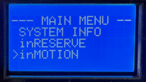
Select inMOTION from the MASTERCELL NGX main menu to begin configuration.
STEP 3. The inSIGHT display shows the inMOTION CONFIG screen. The MASTERCELL NGX scans the CAN network looking for connected inMOTION NGX modules. When it detects exactly one module, the screen reads “Connect only 1 inMOTION to CAN” with “SELECT to go” on the bottom line. Press SELECT to proceed.
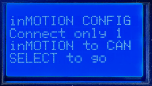
The MASTERCELL NGX confirms it sees exactly one inMOTION NGX on the CAN network.
If the screen displays “Waiting…” instead, the MASTERCELL NGX has not detected any inMOTION NGX modules. Verify that the module has power, is properly grounded and that the CAN wires are correctly spliced to the network.
If the screen shows that more than one inMOTION NGX was found, it will block you from proceeding. Disconnect the extra modules so only one remains on the CAN network, then try again.
STEP 4. The inSIGHT display shows a list of door positions. Use the UP/DOWN buttons to select the position you want to assign to this module: Driver Front, Passenger Front, Driver Rear or Passenger Rear. Press SELECT to confirm your choice.
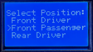
Use UP/DOWN to choose the door position for this inMOTION NGX module.
STEP 5. A confirmation screen appears showing the position you selected. Press SELECT to confirm or HOME to cancel and go back to the position list. Once you confirm, the MASTERCELL NGX sends the configuration commands over CAN. This takes a few seconds while it writes the new settings and verifies the module responds at its new address.
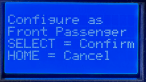
Confirm your selection. Press SELECT to write the configuration or HOME to go back.
STEP 6. When the configuration is complete, the screen displays the new position assignment with a “Success!” message. Press HOME to return to the menu.
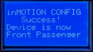
Configuration complete. The inMOTION NGX is now assigned to its door position.
STEP 7. Repeat this process for each inMOTION NGX module in your system. Disconnect the module you just configured from the CAN network, connect the next one and run through the steps again. Continue until every module is assigned to its door position.
Once all modules are configured, reconnect all of them to the CAN network. Navigate to System Inventory on the MASTERCELL NGX to verify that every inMOTION NGX appears at its correct position.
Troubleshooting
The screen says “Waiting…” and never finds my module.
Check that the inMOTION NGX has power on both red 14-AWG wires and is properly grounded on both black 14-AWG wires. Verify that the green and yellow CAN wires are spliced correctly to the IPM1 CAN cable. Make sure the CAN wires are not reversed — green to green (CAN LO) and yellow to yellow (CAN HI).
The screen says it found more than one module.
Only one inMOTION NGX can be on the CAN network during configuration. Disconnect the CAN wires from all other inMOTION NGX modules and try again.
I configured a module to the wrong position.
Run the process again. Connect only that module to the CAN network and assign it to the correct position. The new configuration overwrites the previous one.
Download the Full Manual
This post covers the configuration process for the inMOTION NGX. For complete installation instructions including mounting, power and ground, CAN wiring, output wiring and switch wiring, download the full inMOTION NGX Installation Manual.
Questions?
If you have any questions about how to configure inMOTION NGX modules or anything else about your Infinitybox system, our technical support team is here to help. Give us a call at (847) 232-1991 or fill out our contact form and we will get back to you.
 Copyright 2024, Infinitybox, LLC. All Rights Reserved.