 Copyright 2026 Infinitybox, LLC. All Rights Reserved.
 Messaging Mode on the MASTERCELL NGX
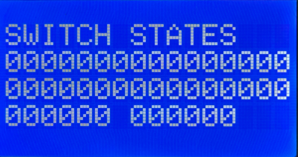
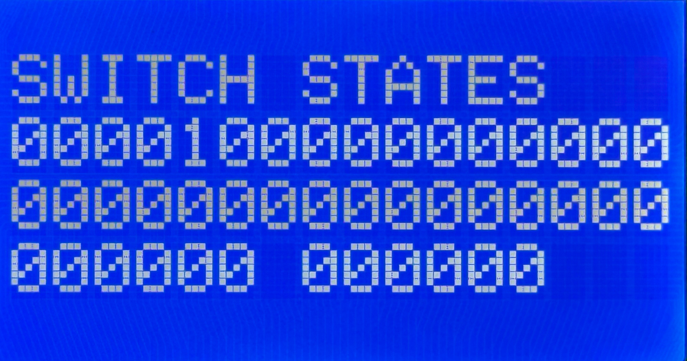
The DEBUG option on your MASTERCELL NGX puts the module into what we call Messaging Mode. It is the deepest diagnostic tool built into the inSIGHT screen. Where the Switch States screen shows you whether an input is on or off, Messaging Mode goes a step further. It shows you what the MASTERCELL NGX does in response to that input, in real time, right on the screen. This blog post is part of our series on the diagnostic functions built into the inSIGHT screen. We introduced this option in our overview of the MASTERCELL NGX main menu, and it works hand in hand with the Switch States screen. In this post, we take a closer look at how to read and use Messaging Mode.
Please note that this blog post covers the MASTERCELL NGX in our Next Generation IPM1 Kit. These inSIGHT diagnostic tools are specific to our Next Generation hardware. If you have our Legacy 3-Cell Kit or 20-Circuit Kit, search through our blog archives for the diagnostic tools that came with those systems.
How Cases Work
To understand what Messaging Mode is showing you, it helps to understand cases. Every input on your MASTERCELL NGX has cases assigned to it. These cases tell the MASTERCELL NGX what messages to send out across the Infinitybox network when that input changes state.
Cases are split into two groups. There are cases for when a switch turns on and cases for when a switch turns off. The number of cases varies from one input to the next. Some inputs have a single ON case and no OFF cases. Others have a single ON case and a single OFF case. Others have multiple ON cases and multiple OFF cases. This is what lets a single switch control multiple outputs across your network at the same time. A simple input like your horn has one ON case that controls one output. A more involved input like your ignition can carry several ON cases and several OFF cases, so turning the key can power your EFI system, bring up accessories in the back of the car and more, all at once.
You can view and modify the cases assigned to each input using our inCODE NGX programming tool. We will cover how to create and change cases in a future blog post and video series dedicated to inCODE NGX. For this post, all you need to know is that cases exist, that they are split into ON and OFF cases, and that the number of cases depends on the input. That is what Messaging Mode puts on the screen.
Entering Messaging Mode
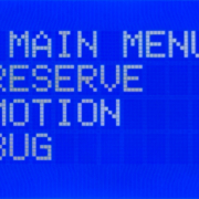
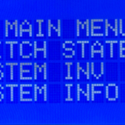
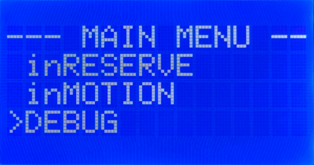
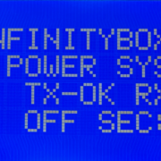
To enter Messaging Mode, press the HOME button on your MASTERCELL NGX to bring up the main menu, scroll to DEBUG and press SELECT. You will see a screen telling you the MASTERCELL NGX is waiting for an input to change.
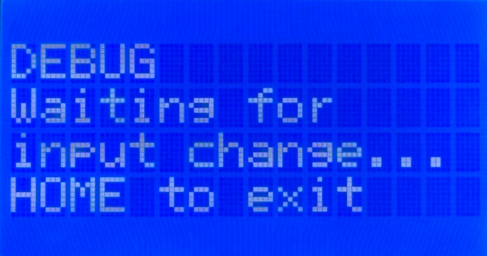
The MASTERCELL NGX in Messaging Mode, waiting for an input to change. Press HOME to exit.
The MASTERCELL NGX stays in Messaging Mode until you press the HOME button, which takes you back to the main menu. While the MASTERCELL NGX is in Messaging Mode, the backlight stays on. This is different from normal operation, where the screen and the backlight both turn off to minimize battery draw. If the backlight is on, you know the MASTERCELL NGX is still in Messaging Mode.
Watching a Single-Case Input
Let’s start with a simple input. On a standard system, your horn is input 9. Always check the configuration sheet that came with your kit to confirm the input and output numbers for your build, because your configuration sheet is the single point of truth for input numbers, output numbers and wire colors.
With the MASTERCELL NGX in Messaging Mode, press the horn button. The screen shows you what the MASTERCELL NGX saw and what it did in response.
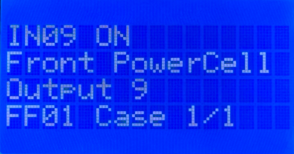
Turning the horn on. Messaging Mode shows input 9 commanding output 9 on the Front POWERCELL.
Reading this screen from the top: the first line, IN09 ON, tells you the MASTERCELL NGX saw input 9 turn on. The second line, Front PowerCell, tells you which cell it is commanding. The third line, Output 9, tells you which output on that cell. The fourth line, FF01 Case 1/1, tells you two things. FF01 is the internal address we use for the Front POWERCELL. Case 1/1 tells you this is case 1 of 1, meaning this input has a single case assigned to its ON state.
Now release the horn button. The screen updates to confirm the input turned off.
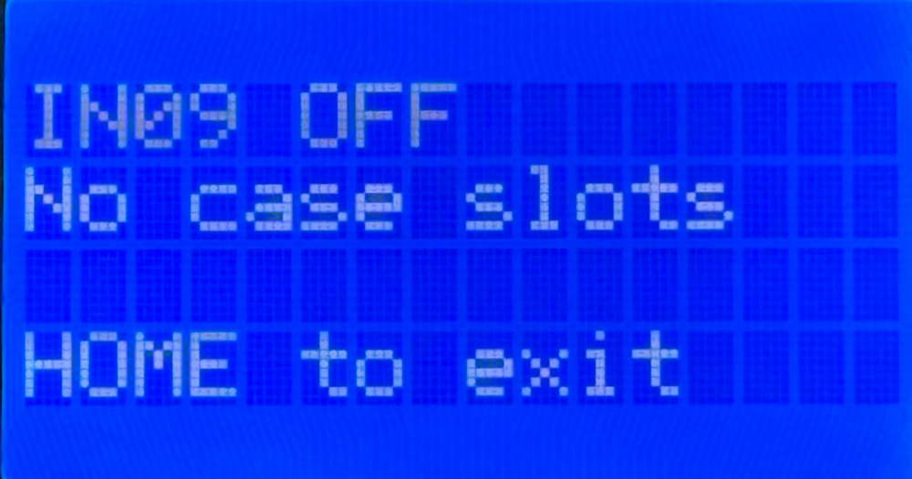
Releasing the horn. Messaging Mode confirms input 9 turned off. The horn input has no OFF case slots.
The first line, IN09 OFF, confirms the MASTERCELL NGX saw input 9 turn off. This is useful on its own, because it confirms the switch released cleanly and is not hung on. The second line reads No case slots. This tells you the horn input has no case slots available for its OFF state. There is nothing for the MASTERCELL NGX to command when the horn turns off, which is exactly how the horn is designed to work.
Watching a Multi-Case Input
Now let’s look at a more involved input. On a standard system, your ignition is input 1. Again, confirm this against your own configuration sheet.
With the MASTERCELL NGX in Messaging Mode, turn the ignition on. The screen shows the first case.
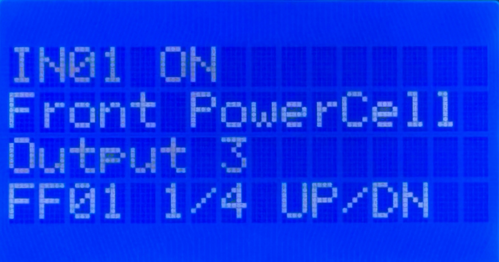
Turning the ignition on. Messaging Mode shows the first of four ON cases, with UP and DN to scroll through the rest.
This screen reads much like the horn did. Input 1 turned on, and the MASTERCELL NGX is commanding output 3 on the Front POWERCELL. The difference is on the fourth line. FF01 1/4 tells you this is case 1 of 4, so this input has four cases assigned to its ON state. The UP/DN prompt tells you to use the SCROLL UP and SCROLL DOWN buttons to step through the rest of the cases. This prompt takes the place of the HOME to exit line, but the HOME button still exits Messaging Mode.
Scroll down to see the next case.
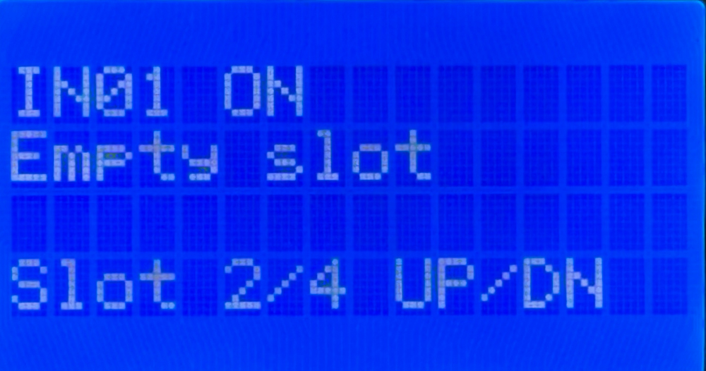
The second slot for the ignition input is empty. Available slots that are not programmed show Empty slot.
This screen shows an empty slot. The default ignition configuration uses only the first ON case, but there are four slots available. The second line reads Empty slot, meaning this slot is available but has nothing assigned to it. Notice the fourth line reads Slot 2/4 instead of leading with an address like FF01. That is because an empty slot has no cell or output assigned to it, so there is no internal address to display.
This is worth pausing on, because it is a different situation from the horn. When the horn turned off, the screen read No case slots, meaning no slots exist for that state at all. Here the screen reads Empty slot, meaning the slot exists and is available, it just has not been programmed. You would keep scrolling to view the remaining slots for this input.
When you turn the ignition off, Messaging Mode confirms the input turned off and shows you the cases assigned to its OFF state.
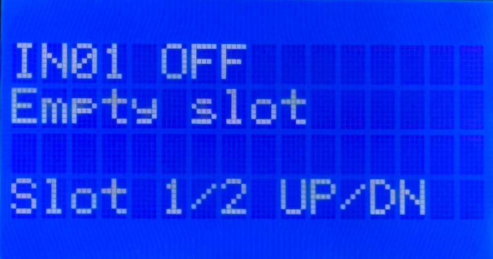
Turning the ignition off. Messaging Mode confirms input 1 turned off and shows two OFF cases to scroll through.
The first line confirms input 1 turned off. The fourth line shows this input has two cases available for its OFF state, with the UP/DN prompt to scroll through them. OFF cases are what let your system do something when a switch turns off, such as running a cooling fan for a set period of time after you shut off the ignition.
What This Tells You
Messaging Mode is one of the most powerful troubleshooting tools in your Infinitybox system because it confirms the whole chain from your switch to your output. Say your horn is not working. Put the MASTERCELL NGX into Messaging Mode and press the horn button. Watching the screen tells you three things at once.
First, it confirms your switch is working. If IN09 ON appears when you press the button, the switch is doing its job and the MASTERCELL NGX is seeing it. If nothing appears, the problem is upstream at the switch or its wiring, not in the rest of the system.
Second, it confirms you have the correct MASTERCELL NGX input wire connected to your switch. If you press the horn button and the screen shows a different input number, you know the wrong input wire is landed on that switch, and you can correct it.
Third, it confirms the correct cell and output are being commanded. The screen shows you exactly which POWERCELL and which output the MASTERCELL NGX is telling to turn on, so you can confirm the command is going where you expect and check your configuration sheet against what you see.
Working through your car this way takes the guesswork out of troubleshooting. Instead of chasing a problem blind, you can watch the MASTERCELL NGX see your switch and command your output, and pinpoint exactly where the chain breaks down.
You can download the entire MASTERCELL NGX inSIGHT document by clicking this link. This includes all the features and functions.
Questions?
Messaging Mode gives you a real-time window into how your MASTERCELL NGX responds to every switch in your car. It is one more diagnostic tool built into the inSIGHT screen to help you wire and troubleshoot with confidence. If you have any questions about Messaging Mode or any other part of your Infinitybox system, contact our technical support team through our contact form or give us a call at (847) 232-1991.
 Copyright 2026 Infinitybox, LLC. All Rights Reserved.
 Copyright 2026 Infinitybox, LLC. All Rights Reserved.
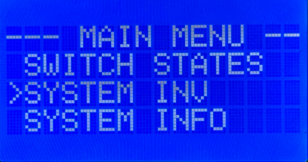
 Copyright 2026 Infinitybox, LLC. All Rights Reserved.
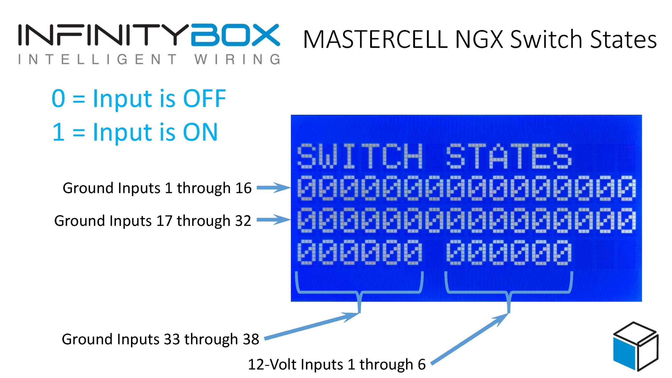
 Copyright 2026 Infinitybox, LLC. All Rights Reserved.
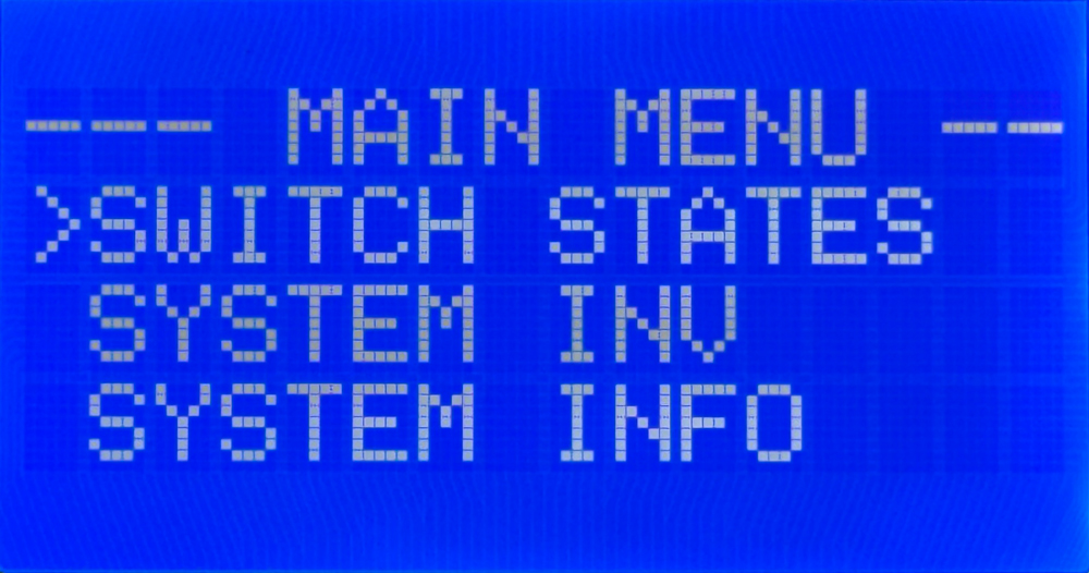
 Copyright 2026 Infinitybox, LLC. All Rights Reserved.
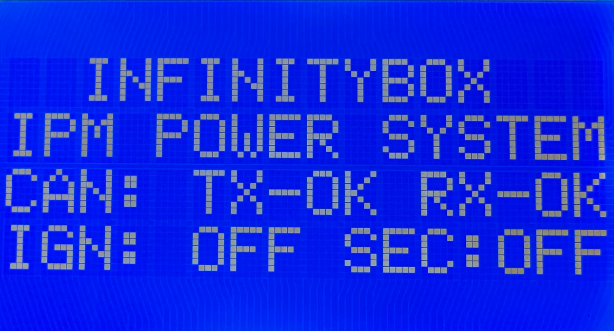

 Copyright 2026 Infinitybox, LLC. All Rights Reserved.
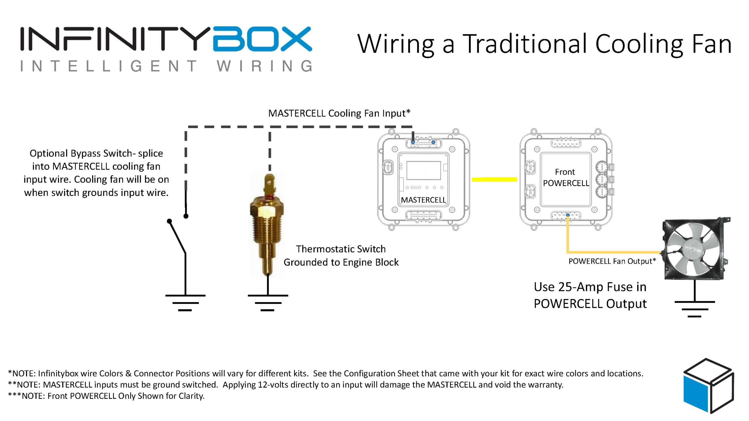
 Copyright 2026 Infinitybox, LLC. All Rights Reserved.