Posts

LS3-powered Brunton Stalker Classic wired with the Infinitybox system

Using Open Outputs

This blog answers a question received from a customer plus shows off the progress on his car.  Mike O just finished his LS3-powered Brunton Stalker Classic.  This is a tribute to the Lotus Super 7.  You can learn more about there car by clicking this link.  His question was about how to use the open outputs on his Infinitybox 20-Circuit Kit.  He wanted to add a water pump and asked if he could use the any of the open outputs to do this.  He also wanted to know how to wire the MASTERCELL inputs to control his open outputs.  We thought that this was a good question that was worth posting up on the blog.

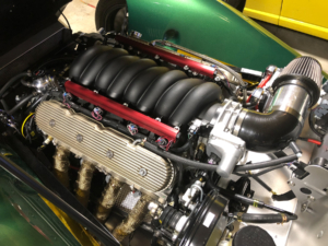
Before we get too technical, let’s talk about the car.  This is another example of a very unique build and shows how simple yet powerful our Infinitybox system can be.  Mike has been working on this car for a while.  He squeezed a 430 hp GM LS3 engine into this chassis all managed by a custom Speartech engine wiring harness.  Considering that the original Super 7’s came with engines the same size as those used in most garden tractors, this LS will make the car fly.

LS3 under the hood of a Brunton Stalker Classic wired with the Infinitybox system

LS3 under the hood of a Brunton Stalker Classic wired with the Infinitybox system

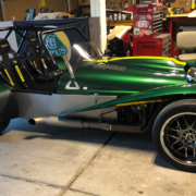
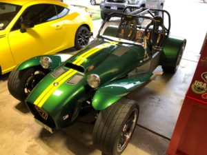
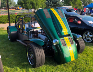
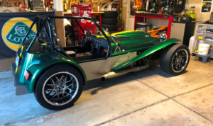
He handcrafted the rear fenders, back panel, cover and rear diffuser out of aluminum.  He custom made the flared wings out of fiberglass.  On top of all of that, he painted it Lotus Racing Green with a yellow racing stripe.  The LS3 is mated to a T-56 6-speed and the brakes are disc from Wilwood.

Brunton Stalker Classic wired with the Infinitybox system

Brunton Stalker Classic wired with the Infinitybox system

Brunton Stalker Classic wired with the Infinitybox system

Brunton Stalker Classic wired with the Infinitybox system

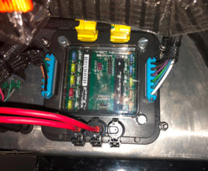
Mike wired the car with our 20-Circuit Kit and inLINK.  The benefit to him was simplifying the wiring, reducing the total amount of wire and giving the flexibility with making changes over his project.  He mounted his MASTERCELL and front POWERCELL just forward of the dash board.  Here is a picture of him laying these out.

MASTERCELL and front POWERCELL installed in Brunton Stalker Classic wired with the Infinitybox system

MASTERCELL and front POWERCELL installed in Brunton Stalker Classic wired with the Infinitybox system

Here is his rear POWERCELL.

POWERCELL mounted in LS3-powered Brunton Stalker Classic

POWERCELL mounted in LS3-powered Brunton Stalker Classic

Okay… now here’s Mike’s question.  He wants to add a Meziere electric water pump to the car.  He originally had a belt-driven water pump.  He wanted to add this electric pump to decrease the load on the engine plus give him more flexibility to cool the car.  Per the manufacturer’s specs, this pump draws 6 to 7-amperes under normal use.  This is well under the 25-amps that a POWERCELL output can supply.

Mike already has the car wired.  With a traditional wiring harness, adding accessories after the fact usually requires running new wires through the car.  With the Infinitybox system, we build in auxiliary outputs that can be used for practically anything.  These outputs can be used for things like extra lighting, multiple fuel pumps, amps, sub woofers and additional cooling fans.  In a typical install, there is 1 open output on the front POWERCELL and 4 on the rear.  Mike simply needs to connect the water pump to the open output on his front POWERCELL.  Then he needs to take the corresponding MASTERCELL input and connect that to a switch for the water pump.  Since he already has the Infinitybox backbone installed in the car, he doesn’t need to run any extra wire through the interior or through the firewall.

The configuration sheet that came with your kit will get you all of the details that you’d need to use these open outputs.  This link will take you to a blog post that gives you more detail on how to read the configuration sheet.  All of the open outputs are set to TRACK.  This means that the output will track the state of the switch.  When the switch is on, the output is on.  When the switch is off, the output is off.  In the case of Mike’s water pump, he can have a switch on the dash what would turn the pump on and off.   He could also wire the MASTERCELL input for his pump directly to the ignition switch so the water pump will turn on when the ignition is on.  You can use this functionality right out of the box with no configuration changes.

We can also custom configure the behavior of these open outputs for you.  One of the most common is to add a timer to the open output used for an electric water pump.  We can set this output to stay on for a period of time after you turn it off.  For example, your electric water pump could continue to run for one minute after the ignition is turned off to help cool down your engine.  Contact our technical support team for more information.

This example shows how flexible and powerful the Infinitybox system can be in your car.  It helped Mike modify the electrical system in his car with minimal changes to add this new water pump.  Thanks to Mike O for asking the question and for sharing the pictures.  The car looks great and we’re proud to be a part of it.

Click on this link to contact our team with any questions about how our Infinitybox system could be used in your project car or truck.

LS3-powered Brunton Stalker Classic wired with the Infinitybox system

LS3-powered Brunton Stalker Classic wired with the Infinitybox system


LS3

GM created something amazing when they introduced their E-Rod crate engine package.  You get the same LS3 powerplant found in the new Camaro and Corvette.  You can drop that into anything that you’re building and get an emissions compliant engine package.

When you buy the E-Rod, you get the option to buy the engine harness for the LS3 direct from GM.  Alternately, you can go with ECUs and engine harnesses from many other manufacturers.  This post is going to talk about how you connect your GM LS3 engine harness to your Infinitybox 10 or 20-Circuit wiring harnesses.

Before you go anywhere, you must thoroughly read and understand the literature that came from General Motors about your LS3 engine and the wiring harness.  This link will take you to the engine control harness literature from GM.

Another important note, this post is only going to talk about connecting the engine harness to the Infinitybox system.  This is going to include the main battery power, the ignition power, the fuel pump trigger and the cooling fan trigger.  Read the GM literature for all of the other electrical connections to the engine.

The first connection that must be made is the primary battery power to the fuse box in the engine harness.  GM recommends an 8-AWG cable running directly from the battery to the main battery connection on the fuse box.  This is a bolted connection on the side of the box.  See the GM literature for proper fusing of this power feed.

There are three ground connections that must be made on the engine harness.  See the GM literature for more specifics on properly connecting these grounds.

Next, you need to connect ignition power from your POWERCELL to the engine harness.  See the configuration sheet that came with your Infinitybox system for the correct wire color for your ignition output.  This will connect to the pink wire in the engine harness.  When your MASTERCELL input for the ignition is triggered, you will have battery power on the POWERCELL output, which will power the ECU.

Next, you need to connect the fuel pump output from the engine harness to your MASTERCELL input.  The GM engine harness puts out a 12-volt signal for the fuel pump trigger.  This must inverted to a ground signal to properly connect to the MASTERCELL.  You can use one of our inVERT Minis to invert this signal.  This link will take you to more information on the inVERT Mini.  You can also use a relay to invert this signal. Different versions of the LS3 engine harness have different colors for the fuel pump wire.  See the GM literature that came with your engine for more details.

Lastly, you need to connect the cooling fan output from the engine harness to your MASTERCELL input.  Just like the fuel pump, the GM engine harness puts out a 12-volt signal for the cooling fan.  Follow the instructions for the fuel pump to properly invert this signal to the MASTERCELL.  Just like the fuel pump, different versions of the LS3 engine harness have different colors for the cooling fan wire.  See the GM literature that came with your engine for more details.

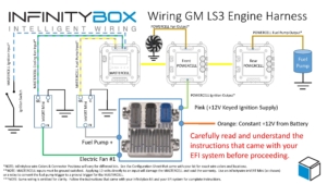
This diagram shows the details of the connections between your Infinitybox system and the LS3 engine harness.

Image of Infinitybox diagram showing how to wire the General Motors LS3 ECU with the 20-Circuit Kit

Image of Infinitybox diagram showing how to wire the General Motors LS3 ECU with the 20-Circuit Kit

You can download a PDF version of this wiring diagram by clicking this link.  

Here’s how the whole thing works.  When you turn on your ignition, the MASTERCELL tells the POWERCELL to turn on the ignition output.  This powers up the engine harness and the ECU.  The ECU will send a signal to the MASTERCELL when it wants the fuel pump to run.  The MASTERCELL will send a signal to the POWERCELL in the rear of the car to provide power to the fuel pump.  When the engine is running, the ECU will send a signal to the MASTERCELL when it is at temperature and the cooling fan should turn on.  The MASTERCELL sends a command to the front POWERCELL to power the fan.  When the engine temperature drops below the set point in the ECU, it will turn off the input to the MASTERCELL.  The MASTERCELL will send a command to the POWERCELL to turn off the cooling fans.

Let us know if you have questions about connecting your E-Rod LS3 engine harness to your Infinitybox system.  Click on this link to get connected to a member of our technical support team.

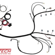
Picture of the Speartech LS-58X Engine Harness

Speartech LS-58X

Our Infinitybox wiring system can interface with practically every engine management system in the aftermarket.  This post is going to show you how to connect your 10 or 20-Circuit Kit to the Speartech LS-58X engine harness.  LS swaps are one of the most popular transplants in resto-mods, street rods and Pro-Touring builds.  Connecting your Infinitybox system to the Speartech LS-58X harness is pretty straight forward.

We get a lot of questions about how our Infinitybox wiring system connects to the ECU.  We don’t control the engine.  That is what the ECU does.  We power the ECU.  We can also take commands from the ECU to control external functions like the cooling fan and fuel pump.

In the case of the Speartech LS-58X engine harness, your Infinitybox system is going to provide the switched key-on ignition power.  It will also take the triggers for the cooling fan and the fuel pump from the ECU.  That way you can use the Infinitybox system to eliminate the need for external relays for your fuel pump and cooling fans.

Before you get any further, please read and understand the manual that came with your Speartech LS-58X harness.  This link will take you to the wiring details from Speartech.  Also, make sure you are familiar with your Infinitybox system.

In this post, we are only going to discuss connecting battery power, ignition power and the triggers for the cooling fan and fuel pump.  Follow the Speartech instructions for the rest of the connections to your ECU and engine.

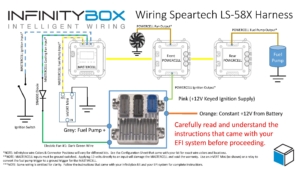
To begin, you have to connect the Orange wire in the Speartech harness directly to your battery.  Follow their instructions for proper connections and proper fuse sizes to protect this wire.

Next, you need to connect the ignition output from your POWERCELL to the Pink wire in the Speartech LS-58X harness.  This is ignition power from the POWERCELL.  When you turn the key to the ignition position, you will get battery voltage to the ECU.

Next, connect the Grey Fuel Pump + wire from the Speartech harness to the MASTERCELL.  This is a positive trigger for the fuel pump so it must be inverted to a ground signal to connect to the MASTERCELL input.  You can use one of our inVERT Minis to do this.  Alternately, you can use a relay to invert this signal.  Click on this link to learn how to use a relay to do this.  You must not connect the MASTERCELL input directly to the Fuel Pump Trigger from the Speartech harness.  This will damage your MASTERCELL input and void the warranty.  Check your configuration sheet for the exact wire colors for your fuel pump trigger.

Last, you need to connect your cooling fan trigger from the MASTERCELL to the Speartech harness.  Check your configuration sheet for the wire colors for your cooling fan input.  The Speartech ECU ground triggers the cooling fan outputs.  That means that you can connect the MASTERCELL input wire directly to the Speartech harness.  The primary cooling trigger from Speartech is the Dark Green wire in their harness.

We strongly recommend soldering a 1N4001 diode in between the MASTERCELL input wire and the EFI system trigger wire for the cooling fan.  This isolates the MASTERCELL from the EFI system.  Diodes are directional parts so you must wire them with the cathode side facing towards the ECU.  That is the side of the diode that has the stripe on it.

The Speartech LS-58X harness has provisions to control two cooling fans.  You can use any OPEN POWERCELL output on your system to control your second cooling fan with the Speartech harness.  Wire the Dark Green wire from the Speartech harness, through the diode as described above, to the MASTERCELL input wire for your second cooling fan.  This way, the Speartech harness will control your primary and secondary cooling fans through your Infinitybox system without having to add relays.

This picture shows the details of wiring the Infinitybox System to the Speartech LS-58X Engine Harness.  Please note that Infinitybox wire colors may vary based on different configurations.  See the configuration sheet that came with your kit for the specific wire colors.

Picture of the Infinitybox wiring diagram showing how to wire the Spear LS-58X Engine Harness

Picture of the Infinitybox wiring diagram showing how to wire the Spear LS-58X Engine Harness

You can download a PDF version of this wiring diagram by clicking this link.

Click this link to contact our team with any questions about wiring your car or truck with our Infinitybox system.