Wiring an Ignition Switch
We’ve been helping guys wire their cars for over 10 years. Sometimes we find ourselves skipping over the basics of how our Infinitybox system works and the advantages that it has over traditional wiring harnesses. A customer called us today with questions about wiring an ignition switch to his MASTERCELL. We were surprised to see that we didn’t have a good wiring diagram nor blog post talking about this. This post will correct that.
The MASTERCELL inputs on an Infinitybox system work by getting connected to ground instead of connecting to battery voltage. This has a bunch of advantages over a traditional wiring harness.
First, the MASTERCELL inputs are just triggers to the system. All of the current is carried by the POWERCELLs. Very little current is required at the MASTERCELL. This means that you can use practically any switch to turn on an input to the MASTERCELL.
Second, since practically no current is required at the switch, the MASTERCELL input wires can be very thin. Our standard input harnesses use 22-AWG wire. This keeps the bulk of the harnessing behind your dash to a minimum.
Lastly, you can easily combine MASTERCELL inputs to a single switch to get more advanced functions without having to change anything in the software.
Click on this link to learn more about how the MASTERCELL inputs work.
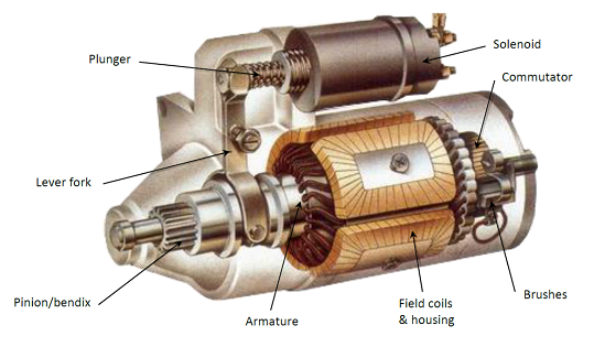
The ignition switch on your car is probably the most important thing. It lets you start and stop the engine. Most ignition switches work the same way. They all have terminals for power, ignition and starter. Some have an additional terminal for powering accessories. This wiring diagram shows how to connect your MASTERCELL inputs to a typical ignition switch.
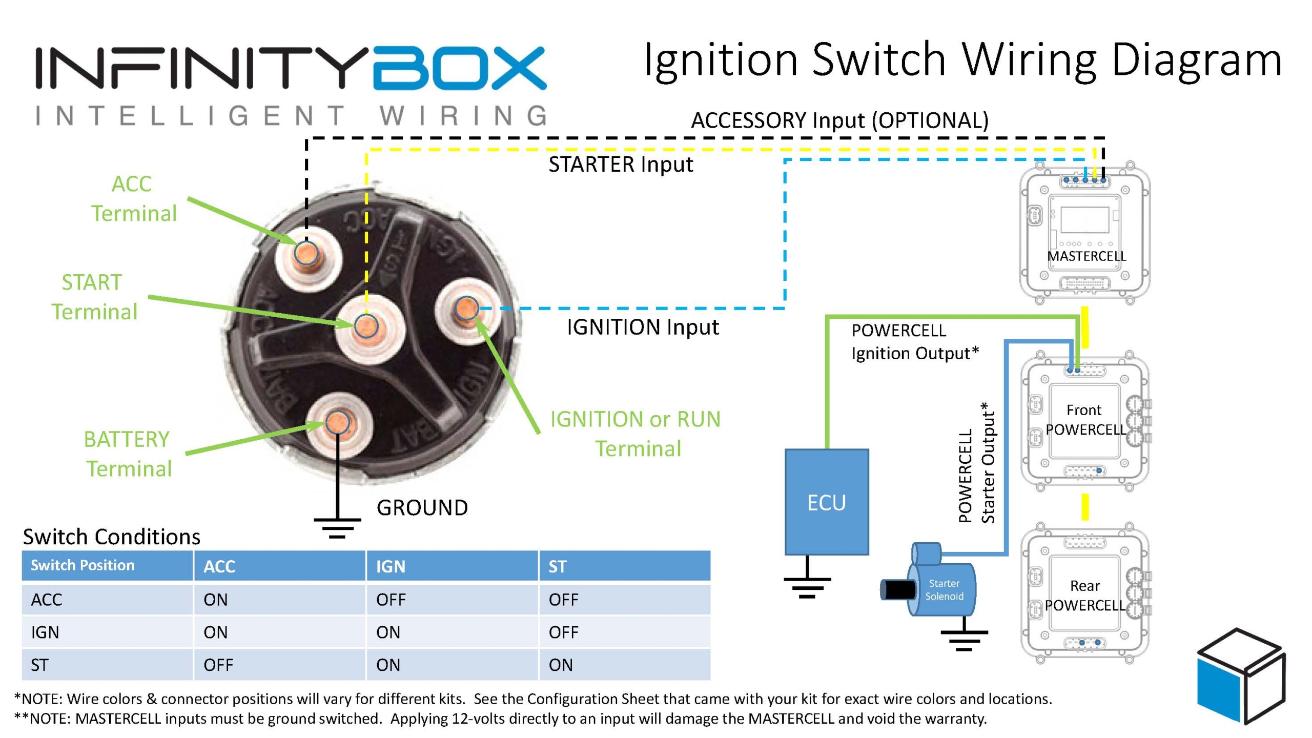
Image of wiring diagram showing how to wire an ignition switch with the Infinitybox system.
As mentioned above, the MASTERCELL inputs work by getting connected to ground. To do this, you are going essentially wire the switch backwards. Instead of connecting the switch to power, you are going to connect it to ground. The first thing to do is connect the battery terminal on the switch to ground. Most switches label this terminal as BAT. Others will label this terminal as B+ or +12V. Look closely at the labels near the terminals to identify the battery terminal. You can either ground this terminal directly to the chassis or you can use one of the black ground wires that is included in the MASTERCELL inputs harness. This ground connection is critical. See our previous posts about how to get good ground connections.
Next, you need to connect the MASTERCELL inputs to the terminals for Ignition and Starter. When the key is in the Ignition position, you need to have power for all of things that run your engine. These include your engine management system, your coils, your gauges and your dash. These are all powered from the Ignition output on your POWERCELL. There is a corresponding MASTERCELL input that turns on this output. Check your configuration sheet to identify these wire colors. Once you know the MASTERCELL input for your Ignition, connect that to the Ignition terminal on the switch. This terminal may be marked as IGN. It could also be marked as RUN. There is an easy way to identify the correct terminal for the Ignition. Turn the key to the Ignition or Run position and measure continuity between the BAT terminal and the IGN terminal. You should have continuity in the run position. It should be open circuit when the key is off.
For the starter input, check your configuration sheet to identify the wire color for the starter. Connect this wire to the ST terminal on your switch.
Lastly, some switches may have an Accessory position on them. This terminal lets you control outputs independently from the ignition. For example, some customers want to be able to power their stereo separately from the ignition so they may listen to music without running their EFI system. The Accessory wires the same way as the ignition and starter. Simply choose an OPEN auxiliary output from your configuration sheet ans connect the corresponding MASTERCELL input to the ACC terminal on the switch. Note that most accessory positions on ignition switches are on in the ACC and IGN positions but off in the START position.
You can download a PDF version of our wiring diagram showing how to wire an ignition switch by clicking this link.
Click this link to contact our technical support team with any additional questions about wiring your car or truck with our Infinitybox system.


 Copyright Infinitybox, LLC 2021. All Rights Reserved.
  Copyright Infinitybox, LLC 2021. All Rights Reserved.


 Copyright Infinitybox, LLC 2021. All Rights Reserved.