Cooling Fan Switch
The next step in our 1967 Mustang wiring process is to wire the cooling fan switch. There are a few different ways to do this depending on how you have your car set up. In a previous post, we talked about wiring the cooling fans to the POWERCELL output. This link will take you to that post. In this post, we are going to talk about wiring the MASTERCELL input wire to trigger the fans.
Remember how our system works. The switches connect to the MASTERCELL. The loads connect to the POWERCELL. There is never a direct connection between the switch and the thing that you are switching. All of that is controlled inside the Infinitybox system.
The most common way to wire the cooling fan switch is to use a temperature switch. This is usually threaded into the radiator. When the coolant temperature exceeds a set point, the switch triggers the cooling fans.
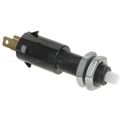
Inside the temperature switch, there is a bi-metal switch that is set for a specific temperature. Typical temperature set points are 180 F, 185 F and 190 F. When the coolant temperature hits this point, the bi-metal element in the switch flips. There are two main different types of temperature switches. The most common has a single terminal on it. This picture shows a common 1-terminal temperature switch.

Example of a typical radiator temperature switch
If you have this type of switch, you are going to connect your MASTERCELL input wire to the quick-disconnect terminal on the switch. The switch grounds to the chassis through its metal body. When the temperature exceeds its set point, the switch closes internally which connects the quick-disconnect terminal to ground. This triggers the MASTERCELL input, which sends a command to the front POWERCELL to turn on the cooling fan output. When the coolant temperature drops below the set point, the switch opens internally. This disconnects the MASTERCELL input from ground. The MASTERCELL sees this change and sends a command to the front POWERCELL to turn off the cooling fan output.
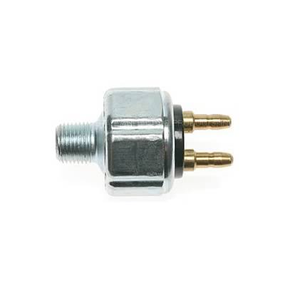
Other temperature switches have two terminals. This picture shows a good example.

Example of a two-terminal temperature switch
In this case, both of the terminals are isolated from the metal body of the switch. You connect your MASTERCELL input to one of the terminals and connect the other terminal to ground. There is no polarity to this switch so you can use either terminal for the MASTERCELL input connection. Outside of that, this switch works the same way as the single terminal switch. When the coolant temperature exceeds its set point, the switch closes internally which electrically connects the two terminals together. This connects the MASTERCELL input to ground.
This picture shows you generically how to wire a temperature switch to your MASTERCELL input.
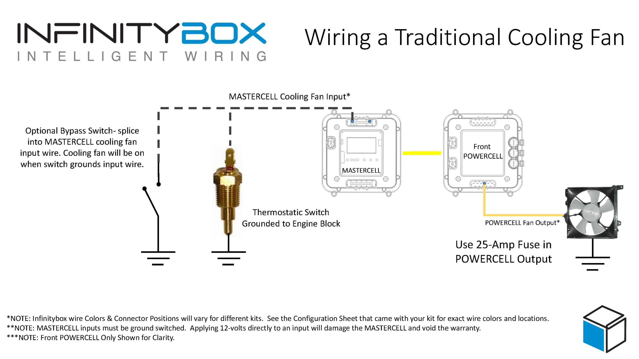
Image of wiring diagram showing how to wire a thermostatic cooling fan switch to the Infinitybox MASTERCELL
Here is an important note about temperature switches and temperature senders. There is a big difference between them. The temperature switch turns on and off at a set temperature. The temperature sender is what controls your temperature gauge. You cannot connect your cooling fan input from the MASTERCELL to your temperature sender.
You can also use your ECU to trigger your cooling fan input if it has that capability. The important thing to understand is whether the ECU trigger is a ground trigger or a positive trigger. The manual for the ECU will get you more information. You need to wire these differently if they are ground or positive triggers. This picture will show you how to wire these two different types of triggers.

Image of wiring diagram showing how to wire the cooling fan trigger from an ECU to the Infinitybox MASTERCELL
If the ECU has a ground trigger for the cooling fan, we recommend installing a diode to buffer the MASTERCELL from the ECU. If it is a positive trigger, you must use a relay or an inVERT Mini to flip the signal to a ground trigger. See the picture above for more details.
Our customer is using the Ford Coyote crate engine in this 1967 Mustang. The Ford ECU has a temperature sender that measures the coolant temperature. Based on this temperature, the ECU has an output that is designed to trigger a cooling fan. We have a dedicated wiring diagram on our website that shows you exactly how to wire the cooling fan trigger to the Coyote ECU. You can download the wiring diagram for the Coyote ECU by clicking this link. The Coyote ECU has a positive cooling fan trigger. You must use an inVERT Mini to flip this signal. The wiring diagram shows you how to do that.
The resources section of our website has wiring diagrams for many different ECUs. These will show you how to wire the cooling fan trigger from the ECU to your MASTERCELL.
Click on this link to contact our team with any questions about wiring your cooling fan switch.
 Copyright Infinitybox, LLC 2021. All Rights Reserved.


 Copyright Infinitybox, LLC 2021. All Rights Reserved.


 Copyright Infinitybox, LLC 2021. All Rights Reserved.