Turn Signals & Brake Lights
We’re making good progress on wiring the outputs on our 1967 Mustang. We’ve made it though headlights, high-beams and parking lights. Now, let’s wire the turn signals and the brake lights. Just like the parking lights, there are turn-signals in the front of the car and the rear. Your 20-Circuit Kit is set up with dedicated outputs on the front & rear POWERCELLs to make wiring these easy. We’re going to talk about wiring the POWERCELL outputs in this post. We’ll get to wiring the inputs in a later post.
Our Infinitybox system has a few advantages over traditional wiring harnesses when it comes to turn-signals and brake lights.
- The flashing is done inside the POWERCELL. You don’t need a separate flasher module to actually blink the turn signals.
- The wiring to the turn signals is much shorter than a traditional wiring harness because you’re connecting the bulbs to the POWERCELL located in the front and rear of the car.
- It doesn’t matter if you are using incandescent bulbs of LEDs. Since the POWERCELL is doing the flashing, you don’t need a load-resistor for LED’s.
- We can manage any different type of turn signal configuration. That is done by picking different MASTERCELL input wires.
For the brake lights, there are two different options. We’ll be the first to admit that this can be a little confusing.
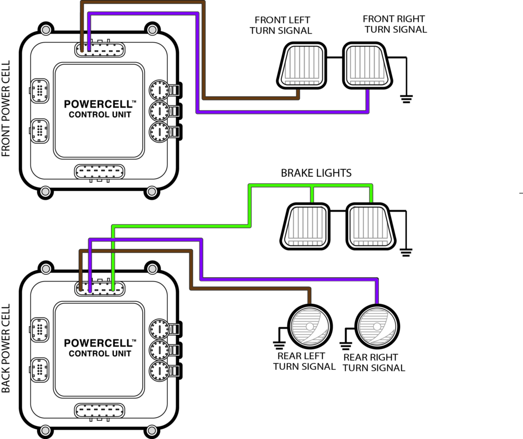
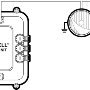
In some cars, you have a separate bulb or filament on a light bulb that is for the brake lights. When you step on the brake light pedal, that switch controls its own light. We call this a multi-filament configuration. There are multiple bulb filaments that handle the turn signals and the brake lights. In this configuration, there is a separate POWERCELL output for the brake lights. This picture shows you the wiring for the multi-filament configuration.
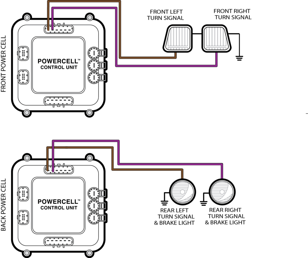
In other cars, the rear turn-signals also work as the brake lights. In this case, you have a single filament that works as both the turn-signal and the brake light. This function was usually managed within the steering column mechanism. We call this a 1-filament configuration or a single-filament configuration. That means there is one bulb filament on the left side and one on the right side of the rear of the car that works as the turn-signal and brake light. If you use our 1-filament configuration, the rear left and right turn-signals will flash when you turn on the left or right turn signal. If you step on the brake pedal, both the left & right turn-signal outputs will turn on together for the brake lights. If you have a turn-signal on and you step on the brake lights, the turn signal will over ride the brake light on that side of the car. This picture shows you the wiring for the 1-filament configuration.
Here’s a good rule of thumb to figure out which brake light configuration you have in your car. If your turn signals are amber, you probably have the multi-filament configuration. There are separate red lights for the brake lights. If your turn-signals are red, you probably have the 1-filament configuration. Those red lights in the corner of the car are both the turn-signals and the brake lights.
Once you figure out the brake light configuration that you have in your car, go to your configuration sheet and pick the POWERCELL output wire colors. In most configurations, the left turn-signal is the brown wire on the front & rear POWERCELL. The right turn-signal is the violet wire on the front & rear POWERCELL. Connect these wires to the left & right turn signals in the front & rear of the car. The POWERCELL output wire goes to one wire on the turn signal bulb. The other wire on the turn signal bulb goes to ground on the chassis. If you are using LED’s make sure that you have the polarity of the bulbs correct. The bulbs will not light if the wires are backwards.
If you are using the multi-filament configuration, you need to splice the brake light output to the brake light bulb on the left & right side of the car. Follow the instructions that we gave in the headlight post for making these splices. If you have a third-brake light or a CHMSL in the car, you can splice off of this same brake light output to power the extra light.
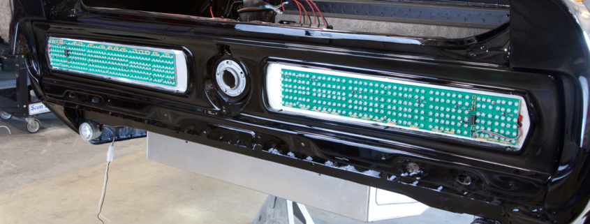
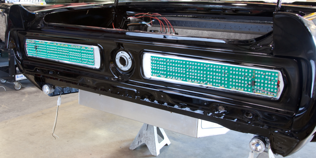
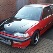
In our customer’s 1967 Mustang, they are using a sequential tail light assembly made by Mustang Projects. You can see the details on that at this link. Their system comes with a very simple manual that shows how to connect the wires for the left turn, right turn and brake lights. This one was wired using the multi-filament configuration which meant that there was a separate output for a brake light. It was very easy. This picture shows the tail light assemblies mounted in the car.
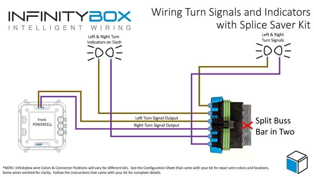
The last step in wiring the turn-signals and the brake lights is to wire the indicators on the dash. You simply splice off the POWERCELL outputs in the front of the car and run 22-AWG wires to the dash indicators. This customer tied into the outputs for the left & right turn-signals, ran these wires to the indicators and grounded the other side of the indicator. They were using LEDs for the indicators so they had to make sure that they had the polarity of the bulbs correct.
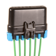
Our Infinitybox Splice Saver Kit is a really simple accessory that can be used to make splicing your turn signals indicators into their respective outputs easy. This picture shows how you can create a sealed junction point with the Splice Saver for your turn signals and their indicators.
That is it for turn-signals and brake lights. Stay tuned for the next posts talking about wiring this 1967 Mustang with our Infinitybox 20-Circuit Kit. If you have questions or comments, please contact us at this link.

 Copyright Infinitybox, LLC 2021. All Rights Reserved.
 Copyright Infinitybox, LLC 2021. All Rights Reserved.
  Copyright Infinitybox, LLC 2021. All Rights Reserved.
  Copyright Infinitybox, LLC 2021. All Rights Reserved.
  Copyright Infinitybox, LLC 2021. All Rights Reserved.
  Copyright Infinitybox, LLC 2021. All Rights Reserved.
  Copyright Infinitybox, LLC 2021. All Rights Reserved.
  Copyright Infinitybox, LLC 2021. All Rights Reserved.
Trackbacks & Pingbacks
[…] from the back of the car up to the front. This may also be an issue if you’re using out 1-filament brake light set up. We’re going to give you a few simple options to get this +12 volt brake light signal from […]
[…] Start by checking the configuration sheet that came with your kit. This link will take you to an earlier post in this series about the importance of your configuration sheet. This car is wired with separate brake light and turn signal outputs on the rear POWERCELL so we’re going to use the MASTERCELL input for Brake Lights with Multi-Filament Bulbs. This post will get you more information on the different turn-signal and brake light options. […]
[…] If you have a dedicated Brake Light bulb in the back of the car, you are going to choose the MASTERCELL input that is called “Brake Lights with Multi-Filament Bulbs”. This means that there is a separate bulb that works as the Brake Lights in the rear of your car. There is a quick rule of thumb that you can use. Use the “Brake Lights with Multi-Filament Bulbs” input if your turn signal lenses are amber. Please read this blog post for more detail. […]
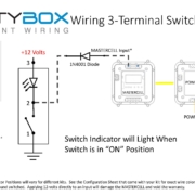
[…] questions from customers asking how to create a clicking sound when their turn signals are on. We’ve blogged before about how to wire the turn signal indicator lights on your dash. This wiring diagram will show you how to get a clicking sound with your turn […]
Leave a Reply
Want to join the discussion?Feel free to contribute!