
Cooling Fan
We’re getting towards the end of the outputs that we need to wire on this 1967 Mustang project. The cooling fan is next. We’ll talk in later posts about how to wire the cooling fan triggers to the MASTERCELL input. This post is going to talk about connecting the POWERCELL output to the fan motor.
In most cars, the cooling fan is connected to the radiator in the front of the car. When the engine coolant temperature exceeds a set point, the cooling fan turns on to blow outside air through the radiator. The fan will continue to run until the coolant temperature drops below a set level.
There is a dedicated output on the front POWERCELL in the 20-Circuit Kit that our customer is installing in this 1967 Mustang. It is output 10, which is the tan wire on the A connector. Check your specific configuration sheet to confirm the wire color.
Our POWERCELL acts as both the fuse and relay box, except we don’t use relays. We use what is called a MOSFET. Think of this as a solid state relay. Each of the outputs on a POWERCELL can carry 25-amps continuously. These outputs can also tolerate in-rush currents up to 100-amps. Like our previous post about headlights and high-beams, you need to consider the in-rush on a motor when you are planning on wiring your car.
When an electric motor is started, the rotor appears to be stalled at the instant the current is applied. This stalled current will flow through the motor windings. As the motor starts to turn, the amount of current flowing to the motor will drop. When the motor reaches its steady-state speed, the current will level off. This initial in-rush current can be 4 to 5 times the steady-state current depending on the size of the motor. The graph below shows an example of this in-rush current.
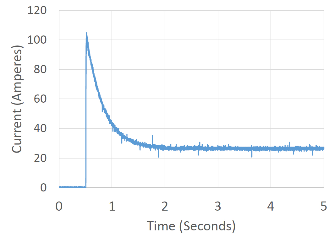
Graph showing the start-up current of a cooling fan
In the case of this fan motor, the initial in-rush is approximately 100-amps. Within 2 seconds of starting, the current levels off at about 25-amps.
In most cooling fans, the manufacturer will tell you that you need to use a 70-amp relay to turn the fan on and off. This is because of the starting current or in-rush current going to the motor. With your Infinitybox system, you can drive most cooling fans directly without adding an external relay. The outputs used in the POWERCELL outputs are designed to handle this in-rush current.
In addition to just handling the in-rush current, we use an extra trick to help manage this in-rush current. As mentioned above, we don’t use relays on our outputs. We use MOSFETs. MOSFETs can be turned on and off thousands of times per second. You can’t do that with a relay. This on and off lets us do something called Pulse-Width Modulation or PWM. There are two important parts of PWM. The first is the frequency. This is how many times you turn the MOSFET on and off each second. Our PWM frequency is 20,000 Hertz. The second part is duty cycle. This is the ratio of the on time over the off time. A 50% duty cycle would have the output on for the same period of time as it is off. A 100% duty cycle means that the output is on all the time. A 0% duty cycle means that the output is off. This picture shows the PWM pulses and different duty cycles.

Examples of three different PWM duty cycles
By changing the duty cycle, we can control the amount of power going to the fan. The higher the duty cycle, the more power is coming out of the POWERCELL output. When we turn on a fan, we soft-start it. This means that we gradually start the fan over about one second. This minimizes the in-rush current.
We get lots of questions about cooling fans and whether or not they can be driven directly from the POWERCELL. Most can. A good rule of thumb is to look at the gauge of wire on the cooling fan. If it is 14-AWG or less, you can certainly use our POWERCELL directly. In most cases, the manufacturer of the fan will publish the running current or steady-state current for the fan. Most commonly used fans in aftermarket applications draw between 8 and 20-amperes.
In some cases, our customers want to use two large fans to cool their engines. The two fans together would draw more than the 25-amps maximum of a single output. In this case, you can use any of the OPEN outputs on your configuration sheet. OPEN means that there is no specific function assigned to them. You can use them as auxiliary outputs. We’ll talk about wiring the cooling fan triggers to the MASTERCELL in a few more posts.
DC fan motors have a direction to them. One of the fan wires will connect to the POWERCELL output and provide battery power to the motor. The second wire must be connected to ground. You must check the manual that came with your fan to determine which wire is power and which is ground. You can also watch the rotation of the motor. Most fan manufacturers put an arrow that indicates the correct direction that it should spin. If the fan spins in the wrong direction, reverse the wires.
You can splice the POWERCELL output wire to the wires on the fan in the same way that we described in our headlight post. You can get to that post by clicking this link.
Keep watching for updates on this 1967 Mustang wiring job with our 20-Circuit Kit. If you have questions or comments, you can click on this link to get in touch with our team.
 Copyright Infinitybox, LLC 2021. All Rights Reserved.


 Copyright Infinitybox, LLC 2021. All Rights Reserved.


 Copyright Infinitybox, LLC 2021. All Rights Reserved.


 Copyright Infinitybox, LLC 2021. All Rights Reserved.


 Copyright Infinitybox, LLC 2021. All Rights Reserved.
 Copyright Infinitybox, LLC 2021. All Rights Reserved.


 Copyright Infinitybox, LLC 2021. All Rights Reserved.
 Copyright Infinitybox, LLC 2021. All Rights Reserved.


