Error Log

There are lots of things that set our Infinitybox wiring system apart from traditional harnesses.  Our troubleshooting and diagnostics is probably one of the most significant features that we offer.  The system will tell you where there are problems in the wiring harness, with no tools required.

One of the more significant features that is built into every one of our systems is our Error Log.  This is an advanced troubleshooting tool that can help to identify problems with a system installed in any vehicle.  The system actively monitors key parameters in the wiring harness.  If these go out of their expected range, the MASTERCELL stores these errors and has the capability to display them back for problem solving.

Let’s start with a deeper dive into how the system works.  When you turn on a switch, the MASTERCELL sees the input get grounded.  It sends a signal to the POWERCELL to turn on an output.  Before the POWERCELL can turn on that output, it needs to check to make sure that everything is safe to do so.  There are three critical parameters that the POWERCELLs check before they can turn on an output: the primary battery voltage, the charge pump voltage and the POWERCELL temperature.  The POWERCELL is continuously monitoring these values and making decision on what to do with them.

The primary battery voltage is an easy one.  The voltage that the POWERCELL is fed from the battery has to be in a specific range.  A charged battery should be at about 12.8 volts.  When the engine is running and the alternator is charging, that voltage should be between 13.8 to 14.2 volts.  The Infinitybox system has internal high and low limits that it watches for the primary battery voltage.  The system can operate down to 6.5 volts and up to 19.0 volts.  If the measured voltage goes outside of these limits, the POWERCELL will shut the outputs off for safety.  In general, your system should be operating between 12.2 and 14.2 volts.  If you’re outside of that, you have a battery or charging issue.

The next one is charge pump voltage.  This is an internal measurement that we take to assess the health of the POWERCELL.  A charge pump is exactly what it sounds like.  We have circuitry on the board that pumps up a charge and stores it.  This stored charge is used to turn the MOSFETs on.  We don’t use relays on the POWERCELL, we use solid-state MOSFETs.  These can do a lot more than a relay but they need to be turned on a specific way.  That’s what the charge pump does.  We monitor the charge pump voltage and display it as part of the POWERCELL statistics.  Depending on the software version, some systems will display CP Volts.  Other systems may display CP Delta.  If  your system shows CP volts, this number should be above 22-volts.  If your system shows CP Delta, it should be above 12.0.  Again, this in an internal measurement that we use to assess the health of the POWERCELL.

The last measurement that we take is board temperature.  Each board has a small temperature sensor mounted on it.  This lets the processor monitor the temperature on the printed circuit board.  This temperature is a combination of the heat generated on the board and the heat from the environment that the POWERCELL is mounted in.  All of the components on the POWERCELL boards are rated to 125 degrees Celsius (257 degrees Fahrenheit).  If the board temperature measured by the processor approaches this 125 C limit, it shuts the outputs down for safety.

So lets look at the error log.  If a POWERCELL records an error, it sends it to the MASTERCELL which stores it in a list.  The MASTERCELL stores 8 errors.  New errors that are recorded push the oldest errors out of this list.  The MASTERCELL reports the Uptime when the error was recorded, the cell that reported it and the outputs associated with it.  The uptime is a clock that starts when the system is powered up.  You can see this when it is running normally.  This is not a real-time clock because it does not continue to run when the system is shut down.

To get to the error log, you first remove the clear cover from the MASTERCELL.  Then you press and release the HOME and SCROLL DOWN buttons under the screen.  Hold them together for one second then let them go.  The MASTERCELL will display any errors that it has stored.  If you want to stop the error log process at any time, simply press and hold the HOME button for 5 seconds.

Our technical support team can learn a lot about your electrical system by looking at the events recorded in the error log.  It is usually easiest for you just to record a video of the error log running with your smart phone and send that to our team.  We can analyze it for you.

By looking at the events in the error log, we can identify problems with your grounds, your battery, your charging system and how you have the system installed in your car.  Check out this video to learn more.


Contact our technical support team if you have any questions about our error log, our diagnostics, our troubleshooting capabilities or any other questions related to our Infinitybox wiring system.

Training inLINK

inLINK is one of our most popular accessories for our 10 and 20-Circuit Harness Kits.  It gets you a very easy way to add an alarm, security and a vehicle immobilizer to your car.  You can either purchase inLINK with your kit up front or you can add at any time down the road.  If you add it down the road, you are going to have to follow these instructions for training inLINK.  This is a simple process that pairs the remote key fob to the radio in the MASTERCELL.

We use a secure and encrypted system to protect the communication between the key fob and the MASTERCELL.  It uses a 64-bit, rolling code encryption scheme.  That means that every time you press a button on the fob, it changes the secret password.  There are billions of combinations of passwords that make hacking into the transmission practically impossible.

Each of the key fobs included with the inLINK kit has to be trained to the MASTERCELL.  If you order inLINK with your 10 or 20-Circuit Harness Kit, we pre-install it and train it for you.  If you order this separately, you need to install the radio board and train the key fobs.

This link will show you how to install the inLINK radio board in your MASTERCELL.

Here are the steps to train your key fobs to your MASTERCELL.

  1. Remove the cover on the MASTERCELL.
  2. Press and release the “TRAIN” button on the MASTERCELL.  You will get a message that will read “To Learn… press any button 2 times”.
  3. Press the lock button on the key fob once, wait one second and press the lock button on the key fob again.  After a few seconds, you will get a message on the screen that reads “Learn Command Accepted”.  You may also get a message that reads “Existing Transmitter Overwritten”.  In either case, the MASTERCELL and key fob are paired.
  4. Repeat this process for the second key fob.

Contact our technical support team with any questions about pairing your inLINK key fobs to the MASTERCELL.

Battery Disconnect

Here’s another good question we got from a customer.

“I normally install in a battery disconnect switch when I wire a car.  When I install inRESERVE, do I need to wire in a separate battery disconnect switch?”

The answer is “no”.  Just like all of our other products, our products are versatile and serve multiple functions.  inRESERVE is our active battery management system.  It works in conjunction with our 10 or 20-Circuit Harness Kits to actively protect your battery from drain.  There are lots of things in your car that are pulling current from the battery when the car sits idle.  The ECU pulls power, the audio system pulls power and our Infinitybox hardware pulls power while the car is sitting.

Before we get into the details of inRESERVE, there are a few things that you can do to maintain the health of your battery and to make sure that you always have a good charge.

First, we always recommend leaving the battery on a maintenance or trickle charger.  Good ones are made by CTEK, Optima or Battery Tender.

From there, we always recommend adding a disconnect switch between the battery and the electrical loads in your car.  That way you can manually kill all of the power demand from your battery when the car is sitting idle.  This is a thing where there are lots of good products out there and lots of bad ones.  The disconnect switches that we recommend are made by Littelfuse or Pollak.  This is one of our favorites.

There are a few important warnings about wiring in disconnect switches.  First, you do not want to run your starter motor through the disconnect.  With the exception of a few switches, most are not designed to handle the current surge from when you crank the engine.  You want to leave the main feed from the battery to the starter motor uninterrupted.  Second, you never want to interrupt the feed from the alternator to the battery.  This can lead to a situation called a load dump and it can cause significant damage to the electrical systems in your car.  This link will get you more information.

Our inRESERVE Active Battery Management System combines a disconnect switch with the intelligence of our Infinitybox system.  Click on this video to learn more about the specifics.

The Infinitybox system is always monitoring the battery voltage in your car.  If the voltage gets too low, a POWERCELL output pulses the special solenoid included in the inRESERVE kit and disconnects all of the draw from the battery.  To do this a few conditions need to be met.  First, the ignition must be off.  We don’t want inRESERVE shutting down power with the ignition on.  Second, the battery voltage must drop below 12.2 volts.  For most battery chemistries, this is less that 10% stored energy.  Lastly, the voltage needs to stay below 12.2 volts for more than 15 minutes.  We do this so that momentary sags in battery voltage will not trigger inRESERVE.

inRESERVE does two very important things by actively disconnecting the battery when the voltage gets low.  First, it always leaves enough of a charge in the battery so that you can crank the engine and get it started again.  Second, it never lets the battery voltage get too low.  Deep cycling of a battery will damage it and will shorten its life.

This link will take you to the wiring diagram for the inRESERVE system.

You will note that there is a manual reset button that is included with the inRESERVE kit.  inRESERVE actively kills power to the system by sending a signal to a special solenoid.  After it does its job, the Infinitybox system is asleep.  You need to manually reset the system by pressing a reset button.  This button must be placed in a location that can be accessed when the battery is disconnected, which means somewhere on the outside of the car if you have power locks or poppers.  We usually recommend installing the button under a fender for easy access.

This same manual reset button can be used to manually disconnect the battery, which is the answer to the question asked at the beginning of this post.  You can press this button to manually disconnect the battery and press it again to reengage the battery, just like a typical battery disconnect switch.  Adding inRESERVE to your system eliminates the need for a manual battery disconnect switch.

There are a few last things to consider when wiring in inRESERVE.

  1. You must not run the starter motor current through this solenoid.  That must run directly between the battery and the starter motor.
  2. You must not run the alternator feed through the inRESERVE solenoid.  The electrical path from the alternator to the battery must not be interrupted.
  3. The solenoid included with the inRESERVE kit is a special solenoid.  It is not like a typical starter solenoid.  It has a special latching mechanism in it.  A momentary pulse to the coil will latch it open.  Another momentary pulse will latch it closed.  Follow the wiring diagram carefully when wiring it.  Also, you may not substitute other solenoids.  They will not work correctly.

Please give our technical support guys a call if you have any questions about wiring a Battery Disconnect into your car.

Harness Connectors

Our Infinitybox 10 and 20-Circuit Kits, plus our Express Racing Kits come with universal harnesses that connect to our MASTERCELLs, POWERCELLs and inMOTION Cells.  We chose the Aptiv family of connector systems for all of our harnesses.  They are cost effective, they are easy to work with, they don’t require expensive tools and they are easy to get through distributors.  Most importantly, they are proven in the field.

Sometimes customers make changes to their harnesses.  Sometimes they damage them and need to repair them.  Sometimes a customer just wants to build their own custom harnesses using the right connectors for the job.  We get asked a lot about the part numbers for these connectors so we just put them up in our Resources Section.  There is a new heading called Connector Components.  That has a complete bill of material for all of the harness connectors used in our system.  You can also get these documents at these links below.

Here is the document for the MASTERCELL.

Here is the document for the POWERCELL.

Here is the document for the inMOTION Cell.

We also get asked where you can buy these harness connectors.  You can get them from many different sources.  We prefer Mouser or Waytek Wire.

Give our technical support team a call if you have any questions about how to work with these connector parts.

Picture of simple leaded LED's

Wiring an LED

We got another great question from a customer today.  This one came in through our Facebook page.

“I’m going to be running LED headlamps and taillights on my Infinitybox-equipped car. Can you write-up a blog on the changes I’ll need to make in my wiring?”

Here are the changes that you need to make when wiring an LED light with the Infinitybox system:  absolutely nothing.

Our POWERCELLs turn things on and off including fans, ECU’s, pumps and lights.  Lights come in basically two flavors: incandescent and LED.  Incandescent lights were the original creation of Thomas Edison.  Up until a few years ago, they were used for all of the lights in cars including headlights, running lights, interior lights, brake lights and turn signals.

The trend in automotive lighting is towards LEDs or light emitting diodes.  This link will take you to a Wikipedia page talking about how they work.  LED’s have two main advantages of incandescent light bulbs.  First, they have no filaments or fragile parts so they last a long time.  Second, they are much more efficient than incandescent bulbs.  This means that they consume much less current to get the same level of brightness.

To go back to the question, you can connect an LED light in the place of an incandescent bulb and it will work correctly when connected to an Infinitybox POWERCELL.  The other question that we usually get related to LED’s is “do I need a load resistor when using LED turn signals?”.  The answer again is “no”.

Traditional turn signal flashers work by drawing current through a heating element within the flasher.  The flashers are expecting a certain amount of current being drawn by an incandescent bulb.  When you change to LEDs with a traditional turn signal flasher, you needed to add a load resistor that draws current through the circuit.  This compensates for the reduced current flowing through the LED.

With the Infinitybox system, you don’t need the load resistor to get your turn signals to work correctly.  We do the flashing of the turn signals and 4-ways through the processor on the POWERCELL.  The flashing does not depend on the amount of current flowing to the bulb.  To the POWERCELL, there is no difference between an incandescent bulb or an LED light.

To round out this question, there is one thing that you may need to do when wiring an LED into your Infinitybox system.  As we mentioned above, LEDs are much more efficient than their incandescent cousins.  It takes very little current to turn them on.  LEDs from different manufacturers are more or less efficient, depending on the materials that they may use.

Our POWERCELLs leak a very small amount of current out of the outputs.  We use this as part of our diagnostic system.  Depending on the efficiency of the LED, this diagnostic current may make the LED’s glow dimly when the light is off.  To eliminate this, you can simply connect a 10K (10,000 ohm) resistor between the POWERCELL output wire and ground.  An 1/8 Watt resistor or larger will be fine.  This picture shows you how to wire this in.

Picture of wiring diagram showing how to wire a bypass resistor with LED lights

Picture of wiring diagram showing how to wire a bypass resistor with LED lights

This bypass resistor shunts the diagnostic current through the resistor around the LED.  You can pick up a 10K resistor on-line.

You can download a PDF of this wiring diagram by clicking this link.

Please give our technical support team a call if you have questions about this post.

Wiring Power Window Switches

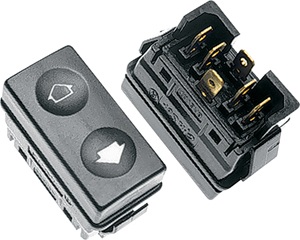
Electric-Life Power Window Switches

Electric-Life Power Window Switches

The inputs to our MASTERCELL are really flexible.  They can connect to practically any switch in your car.  When it comes to wiring power window switches, it is really easy.

Remember that takes a very small current to turn on a MASTERCELL input.  This small current at the switch can be used to control very high levels of current at a POWERCELL.  It can also be used to control large amounts of current through an inMOTION cell plus change polarity output.  You use inMOTION to control things that need to change direction, like power windows, lock actuators, exhaust cutouts and linear actuators.  inMOTION changes the flow of current, which changes the direction of the motion.

A lot of guys ask us how to wire their power window switches to the MASTERCELL inputs.  The answer is very simple.  Remember that the MASTERCELL inputs work by getting connected to ground through the switch.  In most cases, you what was the power feed to the switch to ground, then connect the MASTERCELL input wires to the output terminals on the switch.  In most cases, you can figure this out with a multi-meter set on the resistance setting.  Set the meter to its auto range or its lowest range.  Connect the leads of the meter to the power terminal on the switch and one of the output terminals.  With the switch in the center position, the resistance should be very high.  When you push the switch in one direction, you should see continuity through the switch.  Repeat this process for the other terminal on the switch.

We created an example wiring diagram for the 4920-10-260 power window switch sold by Electric-Life.  These are a very common switch and you see these in lots of cars.  This diagram will show you the terminal that you need to connect to ground and the terminals that you need to connect to your MASTERCELL inputs.  Please note that you must use the wire colors that are detailed in the configuration sheet that came with your kit.

Picture of wiring diagram showing how to connect power window switches to Infinitybox MASTERCELL inputs

Picture of wiring diagram showing how to connect power window switches to Infinitybox MASTERCELL inputs

This link will take you to PDF of this diagram showing you wiring power window switches.

If you have a power window switch that you are trying to figure out, give our team a call at (847) 232-1991.  We are always here to help.

Output Voltage

We get a lot of questions about how the POWERCELL outputs work on our Infinitybox systems.  Here are answers to the two most common questions.

First, a lot of customers ask if we do anything to modify the voltage on the outputs on the POWERCELL when they are on.  The answer is that we do nothing.  The POWERCELL is going to put out whatever voltage it gets in from the battery.  If the battery is low, the POWERCELL is going to output the same low output voltage.  If the alternator is charging, the POWERCELL is going to output the same voltage as the battery is seeing.

The second question that we get from customers is why there is voltage on the POWERCELL output pins when the output is off.  This voltage is part of our diagnostics on the POWERCELL.  When you wire your car with Infinitybox, we give you powerful diagnostic capabilities that you can’t get from a traditional wiring harness.  For our output detection circuit, there is a small amount of current that leaks out of the POWERCELL output.  This is less than 100 micro-amps.  If you have everything connected properly, this leakage current flows through the fuse, through he output connector, through the wire, through the load (light, fan, ECU, etc.) to ground.  If there is a break anywhere in this chain, this leakage current flows back into the LED on the POWERCELL output, causing it to glow dimly.  This is your indicator to check the fuse, look for a break in your harness, check your ground or check for a problem in your load like a burned out light bulb.

If you were to measure the open circuit voltage on a POWERCELL output with a multimeter, you would measure about 2.8-volts.  This is absolutely normal.  Click on this link to download our diagnostics manual to learn more about this.  

If you have any questions about this post or anything else related to wiring your car with our Infinitybox system, give our tech team a call at (847) 232-1991.


Picture of the Littelfuse Minifuse

Fuse Sizes

Here’s the answer to another popular question that we get from customers when they’re wiring their cars with our Infinitybox wiring system.

What size fuse should they use for the different outputs on the POWERCELL?

Remember why the fuse is there…  it is there to protect the wire not the end load.  There is no need to protect the headlamp with a fuse but you do need to protect the wire going to the headlamp.  A fuse is a thermally operating device that is intended to be the weakest point in an electrical system.  If the system is drawing too much current, you want the fuse to open intentionally, protecting the rest of the system.  You never want your wire to be the weakest point in your electrical system.

Fuses are designed to protect against two kinds of faults.  The most common is a short circuit.  Let’s say that the wire to your headlights gets pinched against the chassis and breaks the insulation.  You now have a very low resistance path to ground which will carry a lot of current.  You want the fuse to open before the insulation on the wire gets hot enough to cause damage.  The other scenario is a low-overload.  These are usually resistive connections to ground that will still carry enough current to damage the wire.

To properly select the size of the fuse that you need to consider two things.

First, what is the minimum gauge of wire that the fuse needs to protect?  All of the output harnesses on the Infinitybox POWERCELLs use 14-AWG wire.  But, if you spice our output wire to a wire with a smaller gauge, you need to size the fuse to protect the smaller wire.

Second, you must understand the current draw for your load connected to the output wire.  The fuse must be large enough to handle the steady-state current of the load plus any inrush that the load may have.  Anything inductive (motors, coils, solenoids, etc) have inductive inrushes that could be up to 10 times the steady-state current draw.  Incandescent bulbs also have inrushes.  Remember that the resistance of the filament in the bulb is a function of its temperature.  When the bulb is cold, the resistance is low so it can carry more current.  As the filament heats up, the resistance increases as does the current flowing through the bulb.  The inrush through a light bulb can be 5 to 10 times its steady state current.

For those who want to learn more, this link will take you to a good document from Littelfuse that talks about how to properly size a fuse for a specific application.

LED lights draw far less current than their incandescent brothers and have practically no inrush.  You can use a much smaller fuse.

Here is a simple chart to use as a reference for sizing your fuses.

Headlights- 20-amp
Starter solenoid- 20-amp
Ignition- 25-amp
Fuel pump- 25-amp
High-Beams- 20-amp
Turn-signals- 15-amp
Cooling fan- 25-amp
Power window regulator- 20-amp
Lock actuator- 15-amp
Parking lights- 15-amp
Horn- 10-amp

Use this chart as a guideline to pick your fuse sizes.  You may need to adjust depending on the gauge of wire connected to your load and the specifics of your load.  Remember, these are guidelines.  If you change the gauge of wire that is included in the kit, you have to reevaluate the size of fuse required.

Contact our technical support group at (847) 232-1991 for more details.

Wiring the FAST EZ-EFI

Our Infinitybox wiring harness can be used to provide switch electrical power to just about anything in your car.  This post shows you what you need for wiring the FAST EZ-EFI system.

First, installing any fuel injection system is a process.  Familiarize yourself with the instructions for the EZ-EFI system.  You can download them at this link.

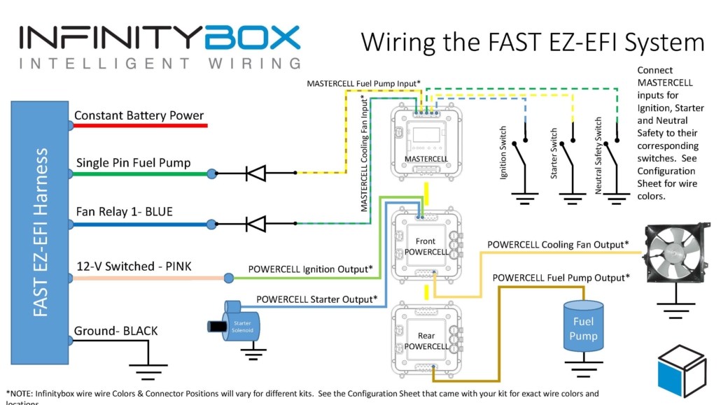
Wiring the EZ-EFI is pretty straight forward.  You are going to use the ignition output on your POWERCELL to supply the switched 12-volts for the EFI system.  The MASTERCELL and POWERCELL in your 20-circuit harness replace the need for the relays to control the fuel pump and the cooling fan.  Connect the wires in their harness per this diagram.

Picture of wiring diagram showing how to wire the FAST EZ-EFI fuel injection system with the Infinitybox system.

Picture of wiring diagram showing how to wire the FAST EZ-EFI fuel injection system with the Infinitybox system.

It is important that you install the diodes that are shown in the diagram.  Our recommendation is to use a 1N4001 diode.  You can purchase these easily on-line.  Please note that the orientation of the diode is important.

You can download a PDF of this wiring diagram by clicking this link.

Give our technical support team a call at (847) 232-1991 if you have questions about wiring the FAST EZ-EFI system.

CAN Cable

The CAN cable is the main backbone of the Infinitybox Multiplex System.  It takes the commands from the MASTERCELL and routes them to the peripheral cells, like POWERCELLs and inMOTION cells, in a system.  We get a lot of questions about this cable and how to work with it so we put this post together to answer these questions.

One of the first questions that we get is what does CAN mean?  CAN stands for Controller Area Network.  This is an automotive standard created to let different electronic systems talk together.  It was originally developed by Bosch in 1983 so it’s been around for a while.  You can read more about CAN at this link.

There area many different CAN protocols.  When a company says they communicate on CAN, that is the equivalent of saying you speak English.  English spoken in the Bronx sounds like someone speaking with a South-Side Chicago accent.  Both use the same basic works but one may not completely understand the other because of inflections and local slang.  The Infinitybox system uses a proprietary version of CAN 2.0b.  We take this standard protocol and all extra data to get more functionality out of the system.  We also have versions of our hardware that communicate on J1939, which is the commercial vehicle CAN standard.

Inside our CAN cable, there are two main wire: CAN High and CAN Low.  These send the commands between the different cells in an Infinitybox system. Additionally, we run a power and ground wire to provide voltage to the MASTERCELL.  The POWERCELLs have the ability to put out voltage through the CAN connector.  There is a very important addendum that we include with our 20-Circuit Harness kits that talks about power and ground in the CAN cables.  Please check out this link when you’re installing your kit.

A lot of guys ask where they can put their different cells on the 3-way cable that comes with the 20-Circuit Kit.  On very long CAN cables, over 30 feet, you need to have the MASTERCELL on one of the cable and the POWERCELL with the terminator resistor on the other end.  This has to do with proper impedance matching of the CAN High and CAN Low lines in the cable.  For most aftermarket installs, where the CAN cable length is under 30 feet, you can put the MASTERCELL anywhere on the CAN cable.

A lot of guys also ask about the length of the CAN cable.  We include a standard CAN cable length in the 10-Circuit and 20-Circuit Harness Kits.  This length was derived from a few years of learning from our customers and how they place cells in their cars and trucks.  We also have options when you order your kits to build custom CAN cable lengths.  You can call our sales team about this.  At the same time, there is nothing keeping you from extending or shortening your CAN cable in the system.  You can do this a few ways.

The first option is to cut the cable and splice in a new length of wire or cut out a length of wire.  There is nothing wrong with this and this is a completely acceptable way to do it.  The wire that we use is 22-AWG TXL wire.  You can buy this wire from a few sources.  We get ours from Waytek Wire and you can buy it in reasonable lengths.  This link will take you to the 22-AWG TXL section of their website.  The colors that we use in our standard CAN cables are black, green, blue and red.

It is very important that you do not cross the wires in the CAN cable.  When you’re reconnecting the connector, make sure that the wires go back where they came from.

If you’re going to splice the cables, we recommend a good butt splice connector and heat shrink.  This link will take you to a good 22-AWG butt splice from Waytek.  An 1/8″ piece of heat shrink over this will keep it protected and insulated.  Here’s a link to heat shrink.  The key to a good splice is a good crimp on the butt splice connector.  The right tool will guarantee a good job and isn’t very expensive.  Here’s a good tool for the crimp.

While a splice is completely acceptable, some guys don’t wan them in their wiring harness.  We get that.  You can create your own custom cable lengths and crimp the terminal right on the end of your wire to connect into the connector.  The connector system used for our CAN cables is very easy to work with and requires no special tools.  This picture shows you all of the parts that go into the CAN connector.

Imaging showing the different components of the Infinitybox CAN connector

Imaging showing the different components of the Infinitybox CAN connector

The yellow part is called the strain relief.  It helps to route the wires out of the connector.  The green part is the seal.  Please note that in some newer systems, the cable seals are black.  It makes the connection between the connector and the mating port on the MASTERCELL or POWERCELL water tight.  The grey part is called the connector.  It holds the terminals from the harness.  The last part is the retainer.  This is the clear clip on the front end of the connector.

The terminals that are used in this harness are made by Aptiv.  Their part number for the terminal is 15435885 and it can be sourced easily from Mouser.  This link will take you there.  This link will take you to a good quality crimp tool for these terminals.

You can cut your CAN cable to length and crimp the terminals onto the wires.  These instructions will show you how to dissemble the connector to plug these terminals into the connector.

First, get a small screw driver and gently pry up on the strain relief clips on the strain relief.  This part opens up like a clam shell.  Next, remove the Retainer from the connector.  Use a small screw driver or your fingernail to pry up on the short sides of the strain relief where it clips on to the grey connector.  Once that is done, you can gently pry up on the terminal retention tabs on the grey connector.  These hold the terminals into the connector.  When you lift them, you can pull the wire with the terminal out through the strain relief.

Reassembly of the connector is just as easy.  Crimp the terminals onto the wires and get ready to put it back together.  Just make sure that you put the right wires back into the right cavities in the connector.  The cavities area marked with an identification number on the inside of the strain relief.  Here’s how the wires should go back in.

5- Black

6- Green

7- Blue

8- Red

Make sure that the terminals are pushed to the front edge of the grey connector.  Once you have all of them in, you can snap the clear retainer back onto the grey connector.  Then close the strain relief using the strain relief clips to hold it closed.

Give our team a call if you have additional questions about working with our CAN cable or the connector components.  You can contact us directly by clicking this link.