Your Infinitybox IPM1 Kit makes it easy to control your cooling fan. The MASTERCELL NGX takes the trigger signal from your temperature switch or ECU. It sends a command over the CAN network to the front POWERCELL to turn the cooling fan on and off. The POWERCELL has the switching and fuse protection built in. This eliminates the need for an external relay and a separate fuse for your cooling fan circuit.
The POWERCELL also soft-starts the cooling fan motor. This reduces the in-rush current when the fan first turns on. Soft-starting lets you drive a larger fan with a smaller gauge of wire. Click here to learn more about the benefits of soft-starting.
There are two main ways to trigger your cooling fan with the MASTERCELL NGX. You can use a traditional thermostatic switch or you can use the trigger from your ECU. The MASTERCELL NGX accepts both ground-switched and high-side switched (12-volt) inputs. This gives you the flexibility to handle either type of trigger without adding external components.
Before you go any further, check the configuration sheet that came with your IPM1 Kit. Your configuration sheet is the single point of truth for the wire colors and connector locations in your system. It will tell you which MASTERCELL NGX input is assigned to your cooling fan and which POWERCELL output drives the fan motor.
The most common way to trigger your cooling fan is with a thermostatic switch. This is a temperature-activated switch that is usually threaded into your radiator or your engine. Inside the switch, there is a bi-metal element that is set for a specific temperature. When the coolant temperature exceeds that set point, the switch closes internally and connects its terminal to ground. When the coolant temperature drops below the set point, the switch opens and disconnects from ground.
This is a ground-switched signal. You are going to connect the MASTERCELL NGX input for your cooling fan directly to the terminal on the thermostatic switch. When the switch closes, it will ground the MASTERCELL NGX input. The MASTERCELL NGX sees this change and sends a command to the front POWERCELL to turn on the cooling fan output. When the switch opens, the MASTERCELL NGX sends a command to turn the output off.
There are two common types of thermostatic switches. The most common type has a single quick-disconnect terminal. This type of switch grounds through its metal body when it threads into the radiator or the engine. You connect the MASTERCELL NGX input wire to that terminal.
The second type has two terminals. Both terminals are isolated from the metal body of the switch. You connect the MASTERCELL NGX input to one terminal and connect the other terminal to ground.
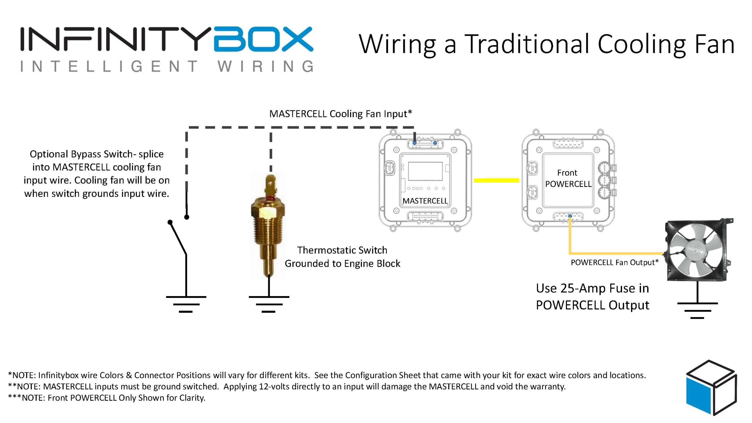
Image of wiring diagram showing how to wire a thermostatic cooling fan switch to the Infinitybox MASTERCELL
Here is an important note about temperature switches and temperature senders. There is a big difference between them. A temperature switch turns on and off at a set temperature. A temperature sender is a variable-resistance device that controls your temperature gauge. You cannot connect your cooling fan input on the MASTERCELL NGX to your temperature sender. They are two separate devices with two separate functions.
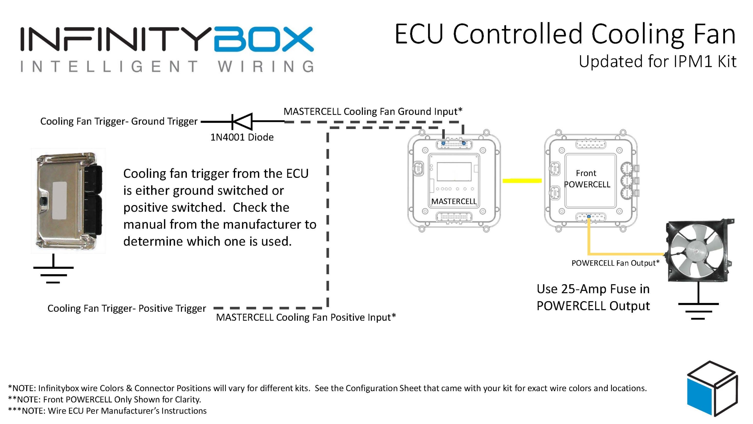
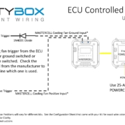
Many modern ECUs and EFI systems have a dedicated output to trigger the cooling fan. The ECU monitors the engine coolant temperature through its own sensor and decides when to turn the fan on and off. If your ECU has this capability, you can wire its cooling fan trigger directly to the MASTERCELL NGX instead of using a thermostatic switch.
The important thing to understand is whether your ECU has a ground-switched trigger or a 12-volt (high-side switched) trigger. Check the manual for your ECU to determine which type of trigger it has. The MASTERCELL NGX can handle both types of triggers natively.
This diagram shows the connections between the thermostatic cooling fan switch, the MASTERCELL NGX, and the front POWERCELL in the Infinitybox IPM1 Kit.
If your ECU has a ground-switched cooling fan trigger, it internally connects the trigger wire to ground when it wants the fan on. You are going to connect this trigger to a ground-switched input on the MASTERCELL NGX.
We always recommend isolating any ground-switched input from an external system like an ECU with a 1N4001 diode. The reason is that we do not know what the ECU does with its trigger when it is off. It may let the trigger voltage float or it may pull the trigger up to battery voltage. Either of these conditions could cause erratic behavior on the MASTERCELL NGX input. To isolate the input, solder a 1N4001 diode in series between the MASTERCELL NGX input and the cooling fan trigger wire on the ECU. Install the diode with the anode facing the MASTERCELL NGX. The orientation of this diode is critical and the system will not work correctly if the diode is wired backwards.
If your ECU has a 12-volt cooling fan trigger, it outputs battery voltage on the trigger wire when it wants the fan on. You are going to connect this trigger to one of the high-side switched inputs on the MASTERCELL NGX.
The MASTERCELL NGX has the ability to accept 12-volt input signals directly on its high-side switched inputs. There is no need for an inVERT Mini or any other external component to flip this signal. This is one of the key advantages of the MASTERCELL NGX in your IPM1 Kit.
You may want to add a bypass switch that lets you turn on the cooling fan manually at any time. This is usually a simple toggle switch on the dash. It gives you the ability to turn the fan on even when the engine is not up to temperature.
To wire a bypass switch, connect a MASTERCELL NGX ground-switched input to one terminal on the toggle switch. Connect the other terminal to ground. You can assign this to the same cooling fan output on the POWERCELL through your inCODE NGX configuration. When you flip the switch, it grounds the MASTERCELL NGX input and turns on the cooling fan regardless of the state of your thermostatic switch or ECU trigger.
Check your configuration sheet for the specific input assigned to your bypass switch.
Once you have the trigger side wired to the MASTERCELL NGX, you need to wire the output side. Connect the cooling fan output on your front POWERCELL to one wire on the cooling fan motor. Connect the other wire on the cooling fan motor to a good chassis ground. Make sure you have a solid metal-to-metal connection with no paint, grease, powder coating, or dirt in the way.
We recommend using a 25-amp fuse in the POWERCELL output to protect the wiring between the POWERCELL and the fan motor. Check your configuration sheet for the specific output and wire color for your cooling fan.
Our resources section has wiring diagrams for many different ECU and EFI systems. These show the specific connections between the ECU and the MASTERCELL NGX for the cooling fan trigger, fuel pump trigger, and ignition power. Check the blog on our website for your specific ECU.
Click here to contact our team or call us at (847) 232-1991 with any questions about wiring your cooling fan with the IPM1 Kit.
Dakota Digital has been in the business of making advanced electrical products for the automotive aftermarket for a long time. Their products include gauges, lighting, cruise control systems, gear indicators, linear actuators, climate control interfaces and other automotive accessories. Their GRFX series represents the latest in their electronic dashboard technology. The GRFX system features full-color TFT displays with user-configurable layouts, themes and colors. A lot of our customers have asked about how to connect their GRFX controller box to our Infinitybox system. This blog post is going to walk you through the details of wiring Dakota Digital GRFX gauges with the IPM1 Kit featuring the MASTERCELL NGX.
This post is specific to our IPM1 Kit with the MASTERCELL NGX. If you have our legacy 20-Circuit Kit or our 3-Cell Kit, the wiring connections are different.
Before we go too far, this post is only going to cover wiring primary power, ground, key-on power, gauge illumination and the signals for the indicators on the dash. Their manual will cover the details for the rest of the wiring. If you are using the VHX or RTX gauges, we have separate posts covering those systems.
The big advantage of the IPM1 Kit is how the MASTERCELL NGX simplifies these connections. The MASTERCELL NGX has built-in low-current indicator outputs. In most installations, the MASTERCELL is located behind the dash — right where the Dakota Digital GRFX controller box is also located. With the IPM1 Kit, you can connect the MASTERCELL NGX indicator outputs directly to the GRFX controller without running wires back to the front POWERCELL. This is a significant wiring simplification compared to the legacy 20-Circuit Kit.
Important: The indicator outputs on the MASTERCELL NGX are limited to 1 amp each. The Dakota Digital documentation shows that the IGNITION PWR terminal on the GRFX controller draws less than 1 amp, which means it can be connected directly to a MASTERCELL NGX output. The turn signal indicators, high-beam indicator and gauge illumination outputs are designed to drive low-current loads. Do not connect anything else to these outputs that could push the total current draw over the 1-amp threshold.
This diagram shows an overview of the connections from the MASTERCELL NGX to the GRFX controller box.
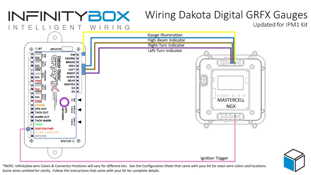
Wiring diagram showing how to wire the Dakota Digital GRFX Controller Box to the Infinitybox IPM1 Kit.
The GRFX controller needs constant power from the battery. Connect the 12 VDC CONSTANT terminal on their controller box directly to the positive terminal on the battery. You must fuse this wire at the battery for safety. Dakota Digital recommends a fused 5 to 20 amp circuit for this connection.
You also have to connect the GROUND terminal on their controller box to a good chassis ground connection. This must be a metal-to-metal connection that is free of paint, powder coating, dirt and debris.
The GRFX controller box needs ignition or key-on power. This is what turns the gauges on when you turn the key in the car. With the IPM1 Kit, your MASTERCELL NGX has a dedicated indicator output for the ignition signal. Connect this output to the IGNITION PWR terminal on the GRFX controller box.
Since the MASTERCELL NGX is located behind the dash, this connection is short and direct. You are connecting two components that are both behind the dash. With the legacy 20-Circuit Kit, this power came from the front POWERCELL ignition output and you had to run a wire from the front of the car back to the GRFX controller behind the dash.
Check the configuration sheet that came with your IPM1 Kit to confirm the specific output assignment for your ignition indicator.
You need to connect the gauge illumination output on the MASTERCELL NGX to the DIM(+) terminal on the GRFX controller box. This will change the display colors and brightness on the GRFX gauges when you have your parking or headlights on.
Again, this is a direct behind-the-dash connection with the IPM1 Kit. The MASTERCELL NGX indicator output for the gauge illumination connects straight to the DIM(+) terminal on the GRFX controller.
Lastly, you need to connect the MASTERCELL NGX indicator outputs for your turn signals and high-beam to their respective terminals on the GRFX controller box. Connect the left turn signal indicator output to the LEFT(+) terminal, the right turn signal indicator output to the RIGHT(+) terminal and the high-beam indicator output to the HIGH(+) terminal.
When the MASTERCELL NGX is commanding the left turn signal, the indicator output will trigger and the left turn signal indicator will flash on the Dakota Digital GRFX display. The same applies for the right turn signal and the high-beam indicator.
These are all low-current indicator signals. The MASTERCELL NGX indicator outputs are purpose-built for this type of connection.
With the legacy 20-Circuit Kit, all of the signals going to the GRFX controller box came from outputs on the front POWERCELL. The ignition power, parking light dimmer, turn signals and high-beam connections all required splicing into POWERCELL output wires at the front of the car and running those wires back behind the dash to reach the GRFX controller. That meant longer wire runs and more splices.
The IPM1 Kit with the MASTERCELL NGX eliminates those long wire runs. The MASTERCELL NGX has built-in low-current indicator outputs that connect directly to the GRFX controller box. Since both the MASTERCELL NGX and the GRFX controller are located behind the dash, these connections are short and direct. You get a cleaner installation with less wiring.
The constant power and ground connections remain the same in both systems. The GRFX controller still gets its constant power directly from the battery and its ground from the chassis.
You can download a PDF of this wiring diagram by clicking this link.
Our technical support team is available to answer any questions about this blog post or any other topics about wiring your car with our Infinitybox system. Click on this link to get in touch with our team.

Dakota Digital has been in the business of making advanced electrical products for the automotive aftermarket for a long time. Their products include gauges, lighting, cruise control systems, gear indicators, linear actuators, climate control interfaces and other automotive accessories. Their RTX gauge family brings classic styling with modern features to any hot-rod, street rod, resto-mod or Pro-Touring build. A lot of our customers have asked about how to connect their RTX gauge controller box to our Infinitybox system. This blog post is going to walk you through the details of wiring Dakota Digital RTX gauges with the IPM1 Kit featuring the MASTERCELL NGX.
This post is specific to our IPM1 Kit with the MASTERCELL NGX. If you have our legacy 20-Circuit Kit or our 3-Cell Kit, the wiring connections are different. Click on this link to get to the wiring diagram for the legacy system.
Before we go too far, this post is only going to cover wiring primary power, ground, key-on power, gauge illumination and the signals for the indicators on the dash. Their manual will cover the details for the rest of the wiring. If you are using the VHX or GRFX gauges, we have separate posts covering those systems.
The big advantage of the IPM1 Kit is how the MASTERCELL NGX simplifies these connections. The MASTERCELL NGX has built-in low-current indicator outputs. In most installations, the MASTERCELL is located behind the dash — right where the Dakota Digital RTX controller box is also located. With the IPM1 Kit, you can connect the MASTERCELL NGX indicator outputs directly to the RTX controller without running wires back to the front POWERCELL. This is a significant wiring simplification compared to the legacy 20-Circuit Kit.
Important: The indicator outputs on the MASTERCELL NGX are limited to 1 amp each. The turn signal indicators, high-beam indicator and gauge illumination outputs are designed to drive low-current loads like LEDs. Do not connect anything else to these outputs that could push the total current draw over the 1-amp threshold.
This diagram shows an overview of the connections from the MASTERCELL NGX to the RTX controller box.
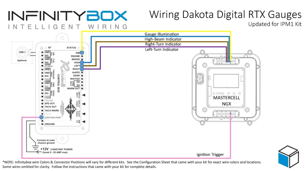
Wiring diagram showing how to wire the Dakota Digital RTX Gauge Controller Box to the Infinitybox IPM1 Kit.
The RTX controller needs constant power from the battery. Connect the 12 VDC CONSTANT terminal on their controller box directly to the positive terminal on the battery. You must fuse this wire at the battery for safety.
You also have to connect the GROUND terminal on their controller box to a good chassis ground connection. This must be a metal-to-metal connection that is free of paint, powder coating, dirt and debris.
The RTX controller box needs ignition or key-on power. This is what turns the gauges on when you turn the key in the car. With the IPM1 Kit, your MASTERCELL NGX has a dedicated indicator output for the ignition signal. Connect this output to the IGNITION PWR terminal on the RTX controller box.
Since the MASTERCELL NGX is located behind the dash, this connection is short and direct. You are connecting two components that are both behind the dash. With the legacy 20-Circuit Kit, this power came from the front POWERCELL ignition output and you had to run a wire from the front of the car back to the RTX controller behind the dash.
Check the configuration sheet that came with your IPM1 Kit to confirm the specific output assignment for your ignition indicator.
You need to connect the gauge illumination output on the MASTERCELL NGX to the DIM terminal on the RTX controller box. This will turn on the illumination on the RTX gauges when you have your parking or headlights on.
Again, this is a direct behind-the-dash connection with the IPM1 Kit. The MASTERCELL NGX indicator output for the gauge illumination connects straight to the DIM terminal on the RTX controller.
Lastly, you need to connect the MASTERCELL NGX indicator outputs for your turn signals and high-beam to their respective terminals on the RTX controller box. Connect the left turn signal indicator output to the LEFT terminal, the right turn signal indicator output to the RIGHT terminal and the high-beam indicator output to the HIGH terminal.
When the MASTERCELL NGX is commanding the left turn signal, the indicator output will trigger and the left turn signal indicator will flash on the Dakota Digital gauges. The same applies for the right turn signal and the high-beam indicator.
These are all low-current indicator signals designed to drive LEDs. The MASTERCELL NGX indicator outputs are purpose-built for this type of connection.
With the legacy 20-Circuit Kit, all of the signals going to the RTX controller box came from outputs on the front POWERCELL. The ignition power, parking light dimmer, turn signals and high-beam connections all required splicing into POWERCELL output wires at the front of the car and running those wires back behind the dash to reach the RTX controller. That meant longer wire runs and more splices.
The IPM1 Kit with the MASTERCELL NGX eliminates those long wire runs. The MASTERCELL NGX has built-in low-current indicator outputs that connect directly to the RTX controller box. Since both the MASTERCELL NGX and the RTX controller are located behind the dash, these connections are short and direct. You get a cleaner installation with less wiring.
The constant power and ground connections remain the same in both systems. The RTX controller still gets its constant power directly from the battery and its ground from the chassis.
You can download a PDF of this wiring diagram by clicking this link.
Our technical support team is available to answer any questions about this blog post or any other topics about wiring your car with our Infinitybox system. Click on this link to get in touch with our team.

Dakota Digital has been in the business of making advanced electrical products for the automotive aftermarket for a long time. Their products include gauges, lighting, cruise control systems, gear indicators, linear actuators, climate control interfaces and other automotive accessories. Their VHX series of gauges has become very popular in the market and a lot of our customers have asked about how to connect their VHX gauge controller box to our Infinitybox system. This blog post is going to walk you through the details of wiring Dakota Digital VHX gauges with the IPM1 Kit featuring the MASTERCELL NGX.
This post is specific to our IPM1 Kit with the MASTERCELL NGX. If you have our legacy 20-Circuit Kit or our 3-Cell Kit, the wiring connections are different. Click on this link to get to the wiring diagram for the legacy system.
Before we go too far, this post is only going to cover wiring primary power, ground, key-on power and the signals for the indicators on the dash. Their manual will cover the details for the rest of the wiring. If you are using the RTX or GRFX gauges, we have separate posts covering those systems.
The big advantage of the IPM1 Kit is how the MASTERCELL NGX simplifies these connections. The MASTERCELL NGX has built-in low-current indicator outputs. In most installations, the MASTERCELL is located behind the dash — right where the Dakota Digital VHX controller box is also located. With the IPM1 Kit, you can connect the MASTERCELL NGX indicator outputs directly to the VHX controller without running wires back to the front POWERCELL. This is a significant wiring simplification compared to the legacy 20-Circuit Kit.
Important: The indicator outputs on the MASTERCELL NGX are limited to 1 amp each. The Dakota Digital documentation shows that the ACC POWER feed draws less than 1 amp, which means it can be connected directly to a MASTERCELL NGX output. The turn signal indicators, high-beam indicator and gauge illumination outputs are designed to drive low-current loads like LEDs. Do not connect anything else to these outputs that could push the total current draw over the 1-amp threshold.
This diagram shows an overview of the connections from the MASTERCELL NGX to the VHX controller box.
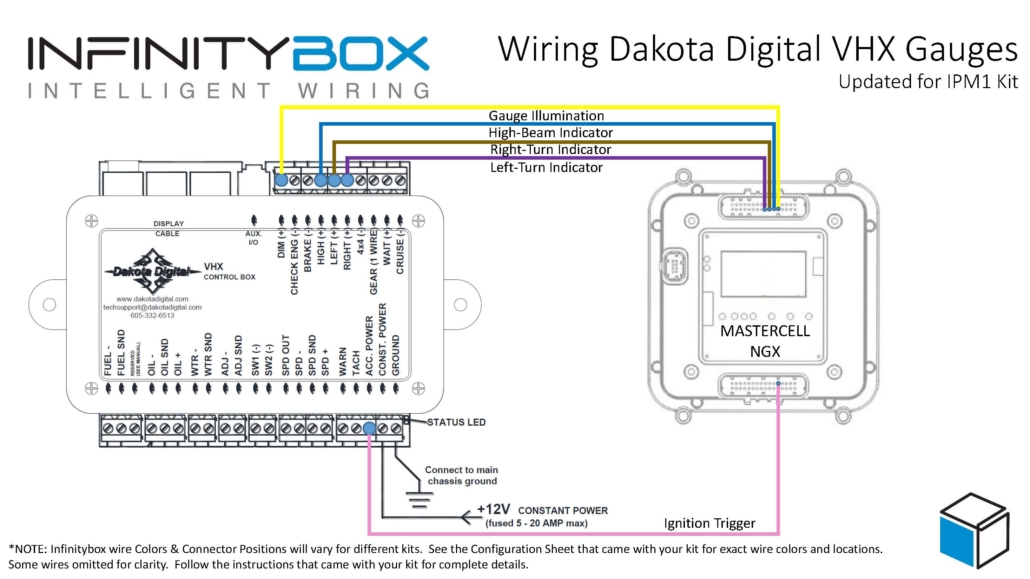
Wiring diagram showing how to wire the Dakota Digital VHX Gauge Controller Box to the Infinitybox IPM1 Kit.
The VHX controller needs constant power from the battery. Connect the CONST. POWER terminal on their controller box directly to the positive terminal on the battery. You must fuse this wire at the battery for safety.
You also have to connect the GROUND terminal on their controller box to a good chassis ground connection. This must be a metal-to-metal connection that is free of paint, powder coating, dirt and debris.
The VHX controller box needs ignition or key-on power. This is what turns the gauges on when you turn the key in the car. With the IPM1 Kit, your MASTERCELL NGX has a dedicated indicator output for the ignition signal. Connect this output to the ACC POWER terminal on the VHX controller box.
Since the MASTERCELL NGX is located behind the dash, this connection is short and direct. You are connecting two components that are both behind the dash. With the legacy 20-Circuit Kit, this power came from the front POWERCELL ignition output and you had to run a wire from the front of the car back to the VHX controller behind the dash.
Check the configuration sheet that came with your IPM1 Kit to confirm the specific output assignment for your ignition indicator.
You need to connect the gauge illumination output on the MASTERCELL NGX to the DIM(+) terminal on the VHX controller box. This will turn on the illumination on the VHX gauges when you have your parking or headlights on.
Again, this is a direct behind-the-dash connection with the IPM1 Kit. The MASTERCELL NGX indicator output for the parking lights connects straight to the DIM(+) terminal on the VHX controller.
Lastly, you need to connect the MASTERCELL NGX indicator outputs for your turn signals and high-beam to their respective terminals on the VHX controller box. Connect the left turn signal indicator output to the LEFT(+) terminal, the right turn signal indicator output to the RIGHT(+) terminal and the high-beam indicator output to the HIGH(+) terminal.
When the MASTERCELL NGX is commanding the left turn signal, the indicator output will trigger and the left turn signal indicator will flash on the Dakota Digital gauges. The same applies for the right turn signal and the high-beam indicator.
These are all low-current indicator signals designed to drive LEDs. The MASTERCELL NGX indicator outputs are purpose-built for this type of connection.
With the legacy 20-Circuit Kit, all of the signals going to the VHX controller box came from outputs on the front POWERCELL. The ignition power, parking light dimmer, turn signals and high-beam connections all required splicing into POWERCELL output wires at the front of the car and running those wires back behind the dash to reach the VHX controller. That meant longer wire runs and more splices.
The IPM1 Kit with the MASTERCELL NGX eliminates those long wire runs. The MASTERCELL NGX has built-in low-current indicator outputs that connect directly to the VHX controller box. Since both the MASTERCELL NGX and the VHX controller are located behind the dash, these connections are short and direct. You get a cleaner installation with less wiring.
The constant power and ground connections remain the same in both systems. The VHX controller still gets its constant power directly from the battery and its ground from the chassis.
You can download a PDF of this wiring diagram by clicking this link.
Our technical support team is available to answer any questions about this blog post or any other topics about wiring your car with our Infinitybox system. Click on this link to get in touch with our team.
Classic cars were simple. An old car with mechanical switches and a set of points had practically no draw from the battery when the ignition was off. The car could sit in a garage for months with no issues. As our customers add computer-controlled EFI systems, audio systems, alarms and our Infinitybox system, the steady-state draw from the battery increases significantly. If the car sits for an extended period, that draw can drain the battery to the point where it will not start. Deep discharging is also detrimental to battery life, shortening the overall lifespan of the battery.
Our inRESERVE Active Battery Management System solves this problem by protecting your battery in two ways. First, it always preserves enough stored energy in the battery to crank the engine and get your car started. Second, it protects the battery from being deep-cycled. Deep cycling a battery can cause permanent damage and dramatically shorten its lifespan. inRESERVE monitors the battery voltage when the ignition is off and disconnects the battery before either of these becomes an issue. This post shows you how to enable inRESERVE on the MASTERCELL NGX in your IPM1 Kit.
The inRESERVE kit includes a latching solenoid that sits between the battery and the rest of the electrical system. The solenoid is a simple mechanical device — the intelligence is in the MASTERCELL NGX. When the ignition is off, the MASTERCELL NGX continuously monitors the battery voltage. If the voltage drops below the threshold for longer than the configured time period, the MASTERCELL NGX commands a POWERCELL output to send a momentary pulse to the solenoid. That pulse latches the solenoid open, disconnecting the battery from the rest of the system and preserving the remaining charge.
The inRESERVE kit also includes a momentary push button. If you know your car will be sitting for a while, you can press the button to manually disconnect the battery before the voltage drops. When you are ready to drive again, press the button to reconnect the battery and you are good to go.
With our legacy 20-Circuit Kit, inRESERVE had to be pre-programmed on the MASTERCELL at the factory. If a customer ordered inRESERVE with their kit, we configured the MASTERCELL before it shipped. If they decided to add inRESERVE later, we had to reprogram their MASTERCELL to enable the feature. This meant extra lead time and coordination.
The IPM1 Kit eliminates that dependency entirely. The MASTERCELL NGX lets you enable inRESERVE yourself, right from the inSIGHT display. You choose the POWERCELL, the output, the timing and the voltage threshold — all without any factory involvement. You can add inRESERVE to your system whenever you are ready.
To enable inRESERVE, your MASTERCELL NGX must be running software version 1.3 or higher. If you are not sure which version you are running, follow the steps in our How to Check the Software Version on Your MASTERCELL NGX post to find out.
You will also need your IPM1 Kit configuration sheet so you can identify which POWERCELL outputs are available for inRESERVE. The available outputs are the OPEN outputs on your configuration sheet. These are universal and auxiliary outputs that are not assigned to fixed functions like turn signals, ignition or starter.
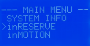
Press and release the HOME button on the MASTERCELL NGX to bring up the Main Menu. Use the SCROLL UP and SCROLL DOWN buttons to move the cursor to the inRESERVE option. Press and release SELECT.
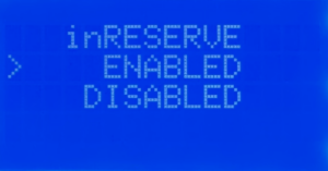
The next screen gives you the option to enable or disable inRESERVE. By default, inRESERVE is disabled. Use the SCROLL UP and SCROLL DOWN buttons to move the cursor to ENABLED. Press and release SELECT.
Next, you need to select which POWERCELL will control the inRESERVE solenoid. You will see options for Front PC, Rear PC and Powercell 3. Choose the POWERCELL that is closest to where the solenoid and battery are located in your car. If the battery is in the trunk, select Rear PC. If the battery is under the hood, select Front PC. The Powercell 3 option is only used for custom configurations developed with our team.
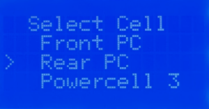
Use the SCROLL UP and SCROLL DOWN buttons to move the cursor to the POWERCELL you want. Press and release SELECT.
The MASTERCELL NGX will show you the available POWERCELL outputs based on which cell you selected in the previous step. These are the OPEN outputs on your configuration sheet. In the standard front-engine configuration, the available outputs on the Front POWERCELL are outputs 7, 8, 9 and 10. On the Rear POWERCELL, the available outputs are 4, 5, 6, 7, 8 and 9.
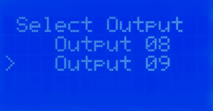
Use the SCROLL UP and SCROLL DOWN buttons to move the cursor to the output you want to use for inRESERVE. Press and release SELECT.
Next, you need to select the time delay. This is the amount of time that the battery voltage must remain below the threshold before inRESERVE activates and disconnects the battery. Your options are 15 minutes and 20 minutes. The default is 15 minutes and we strongly recommend keeping this setting. This gives enough time for brief voltage dips during normal operation without triggering a disconnect.
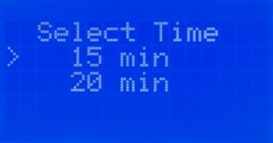
Use the SCROLL UP and SCROLL DOWN buttons to move the cursor to the time you want. Press and release SELECT.
The last setting is the voltage threshold. This is the battery voltage level that triggers the time delay. When the ignition is off and the battery voltage drops below this threshold, the countdown begins. Your options are 12.2V and 12.3V. We strongly recommend 12.2V. This is the standard threshold that we used on our legacy kits and provides the right balance between protecting the battery and avoiding unnecessary disconnects.
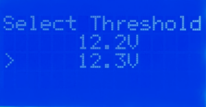
Use the SCROLL UP and SCROLL DOWN buttons to move the cursor to the voltage threshold you want. Press and release SELECT. Your inRESERVE settings are automatically saved when you press SELECT on this final screen.
Once you have enabled inRESERVE on the MASTERCELL NGX, you need to wire the solenoid. The inRESERVE kit includes everything you need: the latching solenoid, a MEGA fuse and fuseholder, a momentary reset button, an inline fuse holder with a 10-amp fuse, ring terminals, terminal boots and 14 AWG wire. Download the inRESERVE wiring schematic for the complete wiring details. Do not run the starter current through the solenoid.
Make sure that the reset button is mounted in an accessible location. When inRESERVE disconnects the battery, the car will have no power. You need to be able to reach the button to reconnect the system. The button included with the kit can be replaced with any momentary button rated to at least 7A at 12V.
If you have any questions about how to enable inRESERVE or anything else about your Infinitybox system, our technical support team is here to help. Give us a call at (847) 232-1991 or fill out our contact form and we will get back to you.
Every IPM1 Kit ships with a base configuration loaded on the MASTERCELL NGX. This configuration is the roadmap that you use to wire your car. It identifies each MASTERCELL input wire, its function and the POWERCELL outputs that it controls. This includes all of the key electrical functions in your car like ignition, starter, turn signals, headlights, parking lights, horn, fuel pump, cooling fans and more.
The configuration sheet is the document that details all of these assignments. It shows you the MASTERCELL input wire colors, the POWERCELL output wire colors and the personalities assigned to each output. This link will take you to an example of the front-engine configuration for the IPM1 Kit. You can learn more about how to read the configuration sheet and understand the POWERCELL output assignments by clicking this link. You should keep your configuration sheet handy throughout your entire wiring project. It is the single most important reference document for your build.
About 95% of our customers use the stock configuration with no changes. For those who need to make modifications, our inCODE NGX programming tool lets you customize your configuration to meet the specific needs of your project.
The IPM1 Kit has two core configurations: front-engine and rear-engine. The main difference between these two configurations is where the ignition and starter outputs are located.
In the front-engine configuration, the ignition and starter outputs are on the front POWERCELL. This makes sense for most builds because the engine is in the front of the car and the POWERCELL that is closest to the engine handles the ignition and starter.
In the rear-engine configuration, the ignition and starter outputs move to the rear POWERCELL. This is the right choice if you are building a mid-engine or rear-engine car like a Factory Five GTM or a Race Car Replicas SL-C. In these builds, the engine is behind the driver and the rear POWERCELL is closest to the engine.
Most of our customers are building front-engine cars, so the IPM1 Kit ships with the front-engine configuration loaded by default. If you are building a mid-engine or rear-engine car, you can easily change this yourself right from the MASTERCELL NGX.
With our legacy 20-Circuit Kit and 3-Cell Kit, we had to pre-program the configuration at the factory before shipping it to you. If you needed a rear-engine setup, you had to let us know when you placed your order and we would program the kit accordingly.
The IPM1 Kit puts this control in your hands. You can select your IPM1 Kit configuration directly from the MASTERCELL NGX without needing to contact us or send anything back. This is a big improvement in flexibility. If you change your mind about your build or want to start fresh, you can reload a configuration yourself at any time.
Please note that this process only works for the MASTERCELL NGX module that comes with the IPM1 Kit. It will not work for the Legacy MASTERCELL that came with the 3-Cell kit or the 20-Circuit Kit. Contact our technical support team if you need support for these legacy systems.
The MASTERCELL NGX has three buttons on the front of the unit: SELECT, SCROLL UP and SCROLL DOWN. You will use these buttons to select your IPM1 Kit configuration. Here are the steps to follow.
Step 1 — Start with the system powered off. Make sure that your MASTERCELL NGX is not powered up. The main power from the battery should be disconnected.
Step 2 — Press and hold the SELECT button. With the system off, press and hold the SELECT button on the MASTERCELL NGX. While you are holding the SELECT button, turn the main power on.
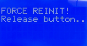
Step 3 — Release the SELECT button. When the MASTERCELL NGX powers up, you will see a screen that says FORCE REINIT! Release button. This tells you that the MASTERCELL NGX is ready to load a new configuration. Release the SELECT button.
Step 4 — Select your configuration. You will see a screen that says Select Config: with three options listed. The options are Front Engine, Rear Engine and Customer. Use the SCROLL UP and SCROLL DOWN buttons to move the cursor to the configuration that you want.
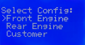
If you are building a front-engine car, select Front Engine. If you are building a mid-engine or rear-engine car, select Rear Engine. Do not select the Customer option unless you have worked with us to create a custom configuration for your project.
Step 5 — Confirm your selection. When the cursor is on the configuration that you want, press and release the SELECT button.
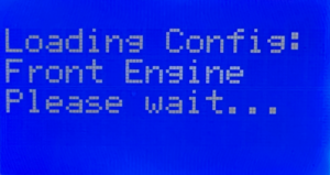
Step 6 — Wait for the configuration to load. You will see a screen that says Loading Config: followed by the name of the configuration that you selected. The MASTERCELL NGX will take about 30 seconds to load the configuration. Do not turn off the power or press any buttons during this process.
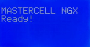
Step 7 — Confirm the configuration is loaded. When the process is complete, the screen will display MASTERCELL NGX Ready! and the main screen will appear. Your configuration is now loaded and you are ready to start wiring.
There are a couple of important things to keep in mind when you select your IPM1 Kit configuration.
First, this process loads the default configuration for the option that you select. If you previously made changes to your configuration using inCODE NGX, those changes will be lost. The MASTERCELL NGX will return to the stock configuration. You will need to re-apply any custom changes with inCODE NGX after the configuration is loaded.
Second, this process only needs to be done if you want to change your configuration. If your kit shipped with the front-engine configuration and that is what you need, you do not need to do anything. Your kit is ready to go right out of the box.
Third, the Customer option on the configuration selection screen is only for customers who have worked with our team to create a custom configuration. If you do not have a custom configuration, do not select this option.
Click this link to contact our team with any questions about how to select your IPM1 Kit configuration.

If you purchased your inMOTION NGX modules before April 1st, 2026, they came preconfigured for a specific door position. You ordered a Driver Front module, a Passenger Front module and so on. Each one was programmed before it shipped.
Starting April 1st, 2026, every inMOTION NGX ships as a universal module. Instead of ordering a door-specific part number, you configure inMOTION NGX modules yourself using the MASTERCELL NGX. This is a one-time setup that takes less than a minute per module. Once configured, the module operates at its assigned door position. You can reconfigure it at any time by running this process again.
This change means you no longer need to worry about ordering the wrong module for a specific door. Every inMOTION NGX in your kit is identical until you tell it where it lives.
You need MASTERCELL NGX software revision 1.4 or higher to use this feature. You can learn how to check your MASTERCELL NGX software version at this blog post.
Before you configure inMOTION NGX modules, make sure the following are done:
You will configure each module one at a time. The MASTERCELL NGX needs to see exactly one inMOTION NGX on the CAN network during this process. That means you will disconnect all but one module, configure it, then move to the next.
Each inMOTION NGX must be assigned to one of four positions. The position determines which CAN address the module uses and which commands it listens to on the network.
| inMOTION NGX Name | Location in Vehicle | CAN Address |
|---|---|---|
| Driver Front | Driver Front Door | 3 |
| Passenger Front | Passenger Front Door | 4 |
| Driver Rear | Driver Rear Door | 5 |
| Passenger Rear | Passenger Rear Door | 6 |
By default, all inMOTION NGX modules ship configured as Driver Front. If you are installing a 2-door vehicle, you only need a Driver Front and a Passenger Front module. For a 4-door vehicle, you will configure all four positions.
STEP 1. Make sure only one inMOTION NGX is connected to the CAN network. Disconnect the CAN wires from all other inMOTION NGX modules. The module that remains connected is the one you are about to configure.
STEP 2. Navigate to the MASTERCELL NGX main menu using the inSIGHT display. Use the UP/DOWN buttons to scroll to inMOTION and press SELECT.
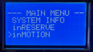
Select inMOTION from the MASTERCELL NGX main menu to begin configuration.
STEP 3. The inSIGHT display shows the inMOTION CONFIG screen. The MASTERCELL NGX scans the CAN network looking for connected inMOTION NGX modules. When it detects exactly one module, the screen reads “Connect only 1 inMOTION to CAN” with “SELECT to go” on the bottom line. Press SELECT to proceed.
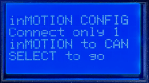
The MASTERCELL NGX confirms it sees exactly one inMOTION NGX on the CAN network.
If the screen displays “Waiting…” instead, the MASTERCELL NGX has not detected any inMOTION NGX modules. Verify that the module has power, is properly grounded and that the CAN wires are correctly spliced to the network.
If the screen shows that more than one inMOTION NGX was found, it will block you from proceeding. Disconnect the extra modules so only one remains on the CAN network, then try again.
STEP 4. The inSIGHT display shows a list of door positions. Use the UP/DOWN buttons to select the position you want to assign to this module: Driver Front, Passenger Front, Driver Rear or Passenger Rear. Press SELECT to confirm your choice.
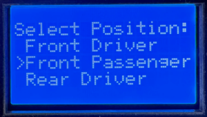
Use UP/DOWN to choose the door position for this inMOTION NGX module.
STEP 5. A confirmation screen appears showing the position you selected. Press SELECT to confirm or HOME to cancel and go back to the position list. Once you confirm, the MASTERCELL NGX sends the configuration commands over CAN. This takes a few seconds while it writes the new settings and verifies the module responds at its new address.
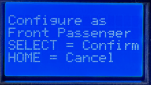
Confirm your selection. Press SELECT to write the configuration or HOME to go back.
STEP 6. When the configuration is complete, the screen displays the new position assignment with a “Success!” message. Press HOME to return to the menu.
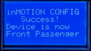
Configuration complete. The inMOTION NGX is now assigned to its door position.
STEP 7. Repeat this process for each inMOTION NGX module in your system. Disconnect the module you just configured from the CAN network, connect the next one and run through the steps again. Continue until every module is assigned to its door position.
Once all modules are configured, reconnect all of them to the CAN network. Navigate to System Inventory on the MASTERCELL NGX to verify that every inMOTION NGX appears at its correct position.
The screen says “Waiting…” and never finds my module.
Check that the inMOTION NGX has power on both red 14-AWG wires and is properly grounded on both black 14-AWG wires. Verify that the green and yellow CAN wires are spliced correctly to the IPM1 CAN cable. Make sure the CAN wires are not reversed — green to green (CAN LO) and yellow to yellow (CAN HI).
The screen says it found more than one module.
Only one inMOTION NGX can be on the CAN network during configuration. Disconnect the CAN wires from all other inMOTION NGX modules and try again.
I configured a module to the wrong position.
Run the process again. Connect only that module to the CAN network and assign it to the correct position. The new configuration overwrites the previous one.
This post covers the configuration process for the inMOTION NGX. For complete installation instructions including mounting, power and ground, CAN wiring, output wiring and switch wiring, download the full inMOTION NGX Installation Manual.
If you have any questions about how to configure inMOTION NGX modules or anything else about your Infinitybox system, our technical support team is here to help. Give us a call at (847) 232-1991 or fill out our contact form and we will get back to you.
Our Infinitybox system can power any ignition and fuel injection system out there. This post covers how to wire the Holley Terminator EFI system with our new IPM1 Kit featuring the MASTERCELL NGX. The wiring approach covered here also applies to the Holley Terminator X and Terminator X MAX systems. We will cover the differences between these systems below. If you have one of our Legacy 20-Circuit Kits, click here to get to the wiring details for that system.
We have blogged before about the Dominator and given detailed instructions on how to wire that system with our 20-Circuit Kit. You can see that here.
Holley makes several versions of the Terminator EFI system. The original Terminator EFI is a self-learning throttle body injection system. The Terminator X is a multi-port fuel injection system designed for LS and LT engine swaps. The Terminator X MAX adds drive-by-wire throttle body control to the Terminator X platform. All three systems use the same types of trigger signals for the fuel pump and cooling fans. That means the wiring approach with your Infinitybox IPM1 Kit is the same across the entire Terminator family.
Your Infinitybox IPM1 Kit is going to provide the ignition power to the Holley ECU. It is also going to take the fuel pump trigger signal from their ECU and the cooling fan trigger. These two triggers will go to the MASTERCELL NGX which will send signals to the POWERCELL in the front of the car for the cooling fan and the POWERCELL in the rear of the car for the fuel pump. This eliminates the need to add external relays because they are switched from inside the POWERCELLs. This also eliminates the need to run high-current wiring from the Holley Terminator EFI system to the front and back of the car. Those signals are sent through our CAN cable.
Before we go any farther, it is very important that you completely read and fully understand the manual that came with your Holley system. There are many different parts of properly installing these systems. The wiring is just one step. Here are links to the Holley manuals:
Once you have read and understand their manual, you must make all of the constant power and ground connections necessary for their system to work. There are multiple constant power feeds that must be wired directly to the battery and multiple ground connections. You must also wire in all of the other connections including the coil, tach, O2 sensors and others. Their manual will cover these details.
Here are the points where your IPM1 Kit will connect to the Holley Terminator EFI system. These same connection points apply to the Terminator X and Terminator X MAX:
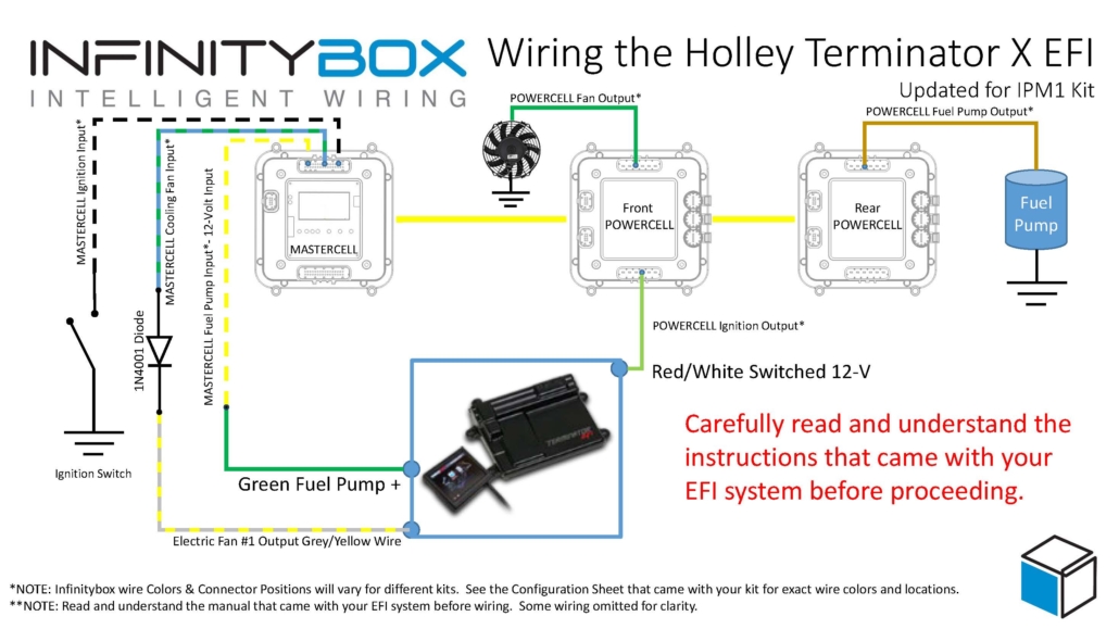
Wiring diagram showing the connections between the Holley Terminator EFI and the Infinitybox IPM1 Kit with the MASTERCELL NGX. This diagram also applies to the Holley Terminator X and Terminator X MAX systems.
You can download a PDF version of this wiring diagram by clicking on this link.
Let’s start with the key-on ignition power. This connection is the same across the original Terminator, the Terminator X and the Terminator X MAX. Check your configuration sheet and find the ignition output wire. In most cases, this is the light-green wire on the front POWERCELL. System configurations may vary so check the configuration sheet that came with your kit. The POWERCELL ignition output wire is going to connect to the red wire with the white stripe in the Holley ECU harness.
The following section covers the fuel pump wiring for the original Holley Terminator EFI. If you have a Terminator X or Terminator X MAX, skip to the Terminator X section below for the details specific to your system.
Next, you need to connect the fuel pump trigger. In the ECU harness, there is a green fuel pump wire. This wire supplies 12-volts to drive a pump directly or to drive a relay coil.
The MASTERCELL NGX in the IPM1 Kit has both ground-switched and high-side switched inputs. The high-side switched inputs accept a 12-volt signal directly. This means you can connect the green fuel pump wire from the Holley Terminator harness directly to a high-side input on the MASTERCELL NGX. There is no need for an inVERT Mini or an external relay to flip this signal. This is one of the key advantages of the MASTERCELL NGX over our legacy MASTERCELL.
Check the configuration sheet that came with your kit. Find the MASTERCELL NGX input for your fuel pump. Confirm the wire color on your configuration sheet as different systems may have different wire colors.
There are several advantages of using the Infinitybox system to control the fuel pump directly from the Holley Terminator harness. First, we can disable the fuel pump as a security measure if you have our inLINK Radio upgrade. More importantly, having the Infinitybox system control the fuel pump means that you have to run less wire in the car. The MASTERCELL NGX is located close to the EFI system. The rear POWERCELL is mounted near the fuel pump in the tank. There is no extra fuel pump wiring required to make it work.
The following section covers the cooling fan wiring for the original Holley Terminator EFI. If you have a Terminator X or Terminator X MAX, skip to the Terminator X section below for the details specific to your system.
Lastly, you need to wire the cooling fan trigger from the Holley Terminator EFI system to your MASTERCELL NGX. The gray wire with the black stripe in the Holley harness is the cooling fan trigger. This is a ground-switched signal so it can connect directly to a ground-switched input on the MASTERCELL NGX.
We recommend installing a 1N4001 diode in series between the MASTERCELL NGX input and the cooling fan trigger on the Holley harness. This diode acts as a one-way valve for the electrical signal. It protects the MASTERCELL NGX input from any voltage surges or back-feeds that could come from the ECU. You can get a 1N4001 diode from any electronics supplier.
Please note that the orientation of the diode is very important. The anode side of the diode connects toward the MASTERCELL NGX and the cathode side connects toward the Holley ECU. The cathode is the side of the diode with the stripe. The stripe on the diode should be on the ECU side of the connection, facing away from the MASTERCELL NGX. Check the wiring diagram above for the correct orientation.
There are several advantages to using the Infinitybox system to control the cooling fan directly off of the Holley Terminator harness. First, you do not need to add a relay. That is built into the POWERCELL. Second, our cooling fan outputs are set to soft-start the motor. Click here to learn more about the benefits of soft-starting.
When you turn the key, the front POWERCELL is going to apply battery power to the ignition input on the Holley Terminator EFI system. When the Terminator wants the fuel pump to turn on, it will send a 12-volt signal to the high-side input on the MASTERCELL NGX. The MASTERCELL NGX will then tell the rear POWERCELL to turn on the fuel pump. When the Terminator wants to turn the cooling fan on, it will send a ground signal to the MASTERCELL NGX. The MASTERCELL NGX will tell the front POWERCELL to turn on the cooling fan.
Holley also makes the Terminator X and the Terminator X MAX. The Terminator X is a multi-port fuel injection (MPFI) system designed for LS and LT engine swaps. The Terminator X MAX adds drive-by-wire throttle body control. Both of these systems connect to the Infinitybox IPM1 Kit using the same wiring approach described above.
The Terminator X and Terminator X MAX have a green fuel pump wire that supplies 12-volts. This is the same type of signal as the original Terminator. Connect this green wire directly to a high-side input on the MASTERCELL NGX. There is no need for an inVERT Mini or an external relay. Please note that the Holley manual states that this green wire can power a fuel pump directly if it draws less than 15 amps. When you are using our Infinitybox system, you are not powering the pump from this wire. You are using it as a trigger signal to the MASTERCELL NGX. The rear POWERCELL will supply the power to run the fuel pump.
The Terminator X also has a separate fuel pump control output on Pin C5 of the I/O connector. This is a dark-blue wire that provides a low-current ground signal. If you prefer to use this output instead of the green wire, you can connect it to a ground-switched input on the MASTERCELL NGX with a 1N4001 diode for protection. Either approach will work. Consult the manual that came with your Terminator X or Terminator X MAX for the details on these wires and their connector locations.
The Terminator X and Terminator X MAX have dedicated cooling fan outputs on their 8-pin I/O connector. These are ground-switched signals that trigger external relays. Since these are ground signals, they connect directly to ground-switched inputs on the MASTERCELL NGX. Install a 1N4001 diode in series for protection, just like the original Terminator. The orientation of the diode is the same. The stripe on the diode faces away from the MASTERCELL NGX, toward the ECU.
The Terminator X and Terminator X MAX support two separate cooling fan outputs from the I/O connector. If you have a dual-fan setup, you can connect both fan outputs to separate inputs on the MASTERCELL NGX and control them independently. This gives you the ability to stage your cooling fans based on the temperature thresholds that you set in the Holley software.
The key-on ignition power connection is the same for the Terminator X and Terminator X MAX. Connect your POWERCELL ignition output to the red wire with the white stripe in the Holley harness. Always check your Infinitybox configuration sheet and the Holley manual to confirm wire colors for your specific system.
If you have one of our Legacy 20-Circuit Kits, the wiring for the Holley Terminator EFI is slightly different. The legacy MASTERCELL only has ground-switched inputs. That means you need an inVERT Mini or an external relay to convert the 12-volt fuel pump trigger from the Holley harness to a ground signal for the MASTERCELL input. Click here to get to the Legacy 20-Circuit Kit wiring details for the Holley Terminator EFI.
The MASTERCELL NGX in the IPM1 Kit eliminates the need for that extra component. Its high-side switched inputs accept 12-volt signals directly. The IPM1 Kit also includes built-in low-current indicator outputs on the MASTERCELL NGX for your dash indicators and the system is fully programmable and configurable by the customer using our inCODE NGX software.
If you have questions about this wiring diagram or wiring anything else with our Infinitybox system, click on this link to contact a member of our team.

Until recently, electronic fuel injection was completely out of the hands of your typical automotive enthusiast. Over the past years, many different companies have introduced powerful and elegant systems to bring the benefits of EFI to anyone. Holley’s Sniper EFI system is one of the most popular. It is a cost-effective throttle body EFI system that can handle up to 650 horsepower and can be tuned without a laptop. Wiring the Holley Sniper EFI system is a breeze with our Infinitybox Intelligent Power Management Kit, the IPM1. This blog post will take you through the details.
Note: This post covers wiring the Holley Sniper EFI with our current IPM1 Kit and the MASTERCELL NGX. If you are wiring the Sniper with our Legacy 20-Circuit Kit, click here to see our original Holley Sniper EFI wiring guide.
If you are familiar with our earlier blog posts, you may have seen our original guide for wiring the Holley Sniper EFI with our Legacy 20-Circuit Kit. We have replaced that kit with the IPM1 Kit, which includes our new MASTERCELL NGX. There are some important differences that simplify how you wire the Sniper EFI.
The biggest change is that the MASTERCELL NGX has both ground-switched and high-side switched inputs. Our Legacy 20-Circuit Kit only had ground-switched inputs on the MASTERCELL. If a trigger from an aftermarket system like the Sniper sent a 12-volt signal, you had to install an inVERT Mini inline to flip that signal to a ground trigger. With the MASTERCELL NGX, high-side switched inputs are built in. The fuel pump trigger from the Sniper EFI is a 12-volt signal. You can now connect it directly to a high-side input on the MASTERCELL NGX without needing an inVERT Mini. This saves you a component and simplifies your wiring.
The MASTERCELL NGX also includes dedicated low-current indicator outputs that can directly drive dash indicators like your turn signal indicators, high-beam indicator, and gauge illumination. On top of that, the MASTERCELL NGX is fully programmable and configurable by the customer.
Our Infinitybox system can interface with any electronic fuel injection system on the market. Wiring the Holley Sniper EFI is as simple as wiring their Terminator or their Dominator. Click on this link to get to the details of wiring the Holley Terminator. Click on this link to get to the details of wiring the Holley Dominator.
Before you start wiring the Holley Sniper EFI, you must thoroughly read and understand the instructions that came with your kit. This link will take you to the Holley manual. Note that this blog post is just going to cover wiring ignition power from your Infinitybox system and wiring the fuel pump and cooling fan. The Holley manual will cover the rest of the wiring details.
This diagram shows you the connections between your Holley Sniper EFI and your Infinitybox IPM1 Kit with the MASTERCELL NGX.
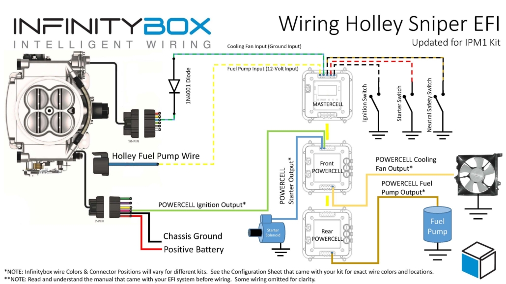
Wiring diagram showing the connections between the Holley Sniper EFI and the Infinitybox IPM1 Kit with the MASTERCELL NGX, including the fuel pump trigger on a high-side input and the cooling fan trigger with a 1N4001 isolation diode.
First things first, you need to get battery power and ground to the Sniper. The red wire in their 7-pin connector must go directly to the positive terminal on your battery. The black wire in their 7-pin connector must go to ground. As we discuss in other blog posts, 90% of all electrical problems relate to a bad ground. Make sure that you have a solid metal-to-metal connection to your chassis with no paint, grease, powder coating, or dirt in the way.
Next, you need to bring ignition power from your POWERCELL to the pink wire on their 7-pin harness. In most Infinitybox systems, this is the light-green wire on your front POWERCELL but check your configuration to be sure. This POWERCELL output will supply battery power to the Sniper whenever you have the ignition switch on.
Next, you need to connect the MASTERCELL NGX input for your cooling fan to the light-blue wire on the Sniper 10-pin harness. The cooling fan trigger from the Sniper is a ground-switched output. Even though the MASTERCELL NGX accepts ground-switched inputs directly, we always recommend isolating any ground-switched input from an external system like the Sniper EFI. The reason is that we do not know what the Sniper does with its trigger when it is off. It may let the trigger float or pull it up to battery voltage. Either of these conditions could cause erratic behavior on the MASTERCELL NGX input.
To isolate the input, you must install a 1N4001 diode in series between the MASTERCELL NGX input and the cooling fan trigger on the Holley harness. Install the diode with the anode facing the MASTERCELL NGX. Note that the orientation of this diode is critical. Check the diagram above for the correct orientation of the stripe on the diode.
There are several advantages to using the Infinitybox system to control the cooling fan directly off of the Sniper harness. First, you do not need to add a relay. That is built into the POWERCELL. Second, our cooling fan outputs are set to soft-start the motor. Click here to learn more about the benefits of soft-starting.
Next, it is time to wire the fuel pump. The dark-blue wire on the 7-pin connector is the fuel pump trigger. This is a 12-volt signal from the Sniper. With the MASTERCELL NGX in your IPM1 Kit, you can connect this fuel pump trigger directly to one of the high-side switched inputs on the MASTERCELL NGX. There is no need for an inVERT Mini. The MASTERCELL NGX has the equivalent of that circuit built into its high-side inputs. This is one of the key improvements over the Legacy 20-Circuit Kit, which required an inVERT Mini inline to convert this 12-volt trigger to a ground signal.
The diagram above shows you how to connect the dark-blue fuel pump trigger wire from the Sniper directly to the high-side input on the MASTERCELL NGX.
There are several advantages to using the Infinitybox system to control the fuel pump directly from the Sniper harness. First, we can disable the fuel pump as a security measure if you have our inLINK Radio upgrade. More importantly, having the Infinitybox system control the fuel pump means that you have to run less wire in the car. The MASTERCELL NGX is located close to the EFI system. The rear POWERCELL is mounted near the fuel pump in the tank. There is no extra fuel pump wiring required to make it work.
Wiring the Holley Sniper EFI system with your Infinitybox IPM1 Kit and the MASTERCELL NGX is straightforward. The high-side switched inputs on the MASTERCELL NGX eliminate the need for an inVERT Mini on the fuel pump trigger, which simplifies your wiring. Remember to isolate the ground-switched cooling fan trigger with a 1N4001 diode to protect the MASTERCELL NGX input.
You can download a PDF of our wiring diagram by clicking this link.
 Copyright 2026 Infinitybox, LLC. All Rights Reserved.
 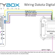 Copyright 2026 Infinitybox, LLC. All Rights Reserved.
 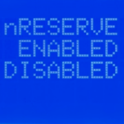 Copyright 2026 Infinitybox, LLC. All Rights Reserved.
  Copyright 2026 Infinitybox, LLC. All Rights Reserved.