Posts

MASTERCELL NGX System Inventory

The System Inventory screen on your MASTERCELL NGX gives you a list of every device connected on your Infinitybox network. It is a simple but powerful tool that confirms your POWERCELLs, inMOTION Cells and other peripherals are connected, communicating and addressed correctly. This blog post is part of our series on the diagnostic functions built into the inSIGHT screen. We introduced this screen in our overview of the MASTERCELL NGX main menu. In this post, we take a deeper look at how to read and use the System Inventory screen.

Please note that this blog post covers the MASTERCELL NGX in our Next Generation IPM1 Kit. These inSIGHT diagnostic tools are specific to our Next Generation hardware. If you have our Legacy 3-Cell Kit or 20-Circuit Kit, search through our blog archives for the diagnostic tools that came with those systems.

How to Read the System Inventory Screen

To get to the System Inventory screen, press the HOME button on your MASTERCELL NGX to bring up the main menu, use the SCROLL UP and SCROLL DOWN buttons to move the cursor to System Inv and press SELECT.
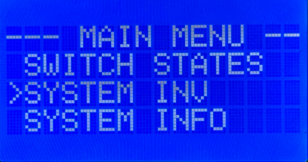
MASTERCELL NGX inSIGHT main menu with the cursor on the System Inv option.

Selecting System Inv from the MASTERCELL NGX main menu.

When the screen opens, you will see a list of every device that the MASTERCELL NGX finds on your network. The header at the top of the screen reads SYSTEM INV followed by a number in parentheses. That number tells you how many devices are on the network. It will change with the number of devices that are connected. In the example below, the header reads SYSTEM INV (3), so there are three devices on the network.
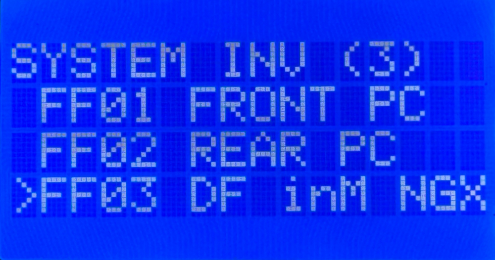
System Inventory screen on the MASTERCELL NGX inSIGHT display showing three connected devices with their PGN and name.

The System Inventory screen showing three devices on the network: a front POWERCELL, a rear POWERCELL, and a Driver Front inMOTION NGX.

Each device shows up on its own row with two pieces of information. On the left is the PGN for that device. This is an internal identifier that the MASTERCELL NGX uses to validate the device on the network. You do not need to decode it. On the right is the human-readable name that tells you what the device is. This is the part you will use to confirm what is connected.

You can use the SCROLL UP and SCROLL DOWN buttons to move the cursor through the list of devices. In this separate blog post, we show you how to use the SELECT button to drill down into a specific device and see much more detail about it, like the state of its outputs and its voltage. For this post, we are focused on the inventory list itself.

What the Devices Look Like on the Network

Each type of device in the Infinitybox system shows up in inventory with its own name so you can identify it at a glance. Here is what the different devices look like on the network.

  • POWERCELLs:
    • Address 1 shows as the front POWERCELL (FRONT PC)
    • Address 2 shows as the rear POWERCELL (REAR PC)
    • Additional POWERCELLs begin at FF07 and are labeled by number, such as POWERCELL 3
  • inMOTION Cells (FF03 through FF06):
    • Driver Front- DF inM NGX
    • Passenger Front- PF inM NGX
    • Driver Rear- DR inM NGX
    • Passenger Rear- PR inM NGX
  • inVIEW: inVIEW
  • inCONTROL: inCONTROL

Confirm Your Devices Are Connected and Communicating

The first thing the System Inventory screen tells you is whether every device you installed is actually on the network. When a device is powered correctly and its CAN cables are connected correctly, it announces itself to the MASTERCELL NGX and shows up in inventory.

Start with the device count in the header. Compare the number in parentheses to the number of devices you installed in your car. If you installed three POWERCELLs but the header only shows two, then one of them is not communicating. The same is true for any device in your system.

When a device is missing from inventory, it usually points to one of two things. Either the device is not being powered correctly, or there is a problem with the CAN cable that connects it to the rest of the network. The System Inventory screen lets you confirm quickly that every device is present before you spend time chasing a problem somewhere else.

Confirm Your Devices Are Addressed Correctly

The second thing the System Inventory screen tells you is whether each device is addressed as the device you intended. This is a more subtle problem, and it is one that can be very hard to find any other way.

Every POWERCELL is set to a specific address with its address jumpers. The MASTERCELL NGX sends commands to each POWERCELL based on that address. If a POWERCELL is addressed incorrectly, the commands meant for it never reach it, even though everything is powered and communicating perfectly.

Here is a common example. A customer is having trouble getting the outputs on a POWERCELL to work. Everything is wired correctly and the cell is communicating, but the functions still do not work. After some troubleshooting, we find that the address jumpers were set to the wrong cell. Instead of being set to cell 1, the POWERCELL was set to cell 8. The System Inventory screen makes this easy to spot. The customer can look at inventory and see that a device is on the network, but it is not showing up as the cell they intended it to be. That tells them the address is wrong.

This is what makes the System Inventory screen so powerful. It takes an invisible problem, a device that is powered and communicating but addressed incorrectly, and makes it visible. We will cover how to set and change device addresses in more detail in a later blog post.

Summary

The System Inventory screen on the MASTERCELL NGX inSIGHT display gives you a quick, at-a-glance list of every device on your Infinitybox network. Use it to confirm that every device you installed is powered and communicating, and to confirm that each device is addressed as the cell you intended. Paired with the other diagnostic tools on the inSIGHT screen, it is one of the fastest ways to understand what is happening on your network.

You can download the entire MASTERCELL NGX inSIGHT document by clicking this link.  This includes all the features and functions.

Keep watching our blog for more details on the menus and diagnostic functions on the inSIGHT screen. If you have any questions, give us a call at (847) 232-1991 or contact us here.
MASTERCELL NGX Main Screen

The inSIGHT LCD screen on your MASTERCELL NGX is your window into your Infinitybox system.  With a few simple button presses, the screen lets you set up your IPM1 kit plus gives you powerful diagnostic tools.  We’ve talked about the features under the cover of your MASTERCELL NGX in a separate blog post.  You can learn about the inSIGHT screen, the menu buttons and other features by clicking this link.  In this post, we want to talk about the main screen on your MASTERCELL inSIGHT screen.  Please note that this blog post discusses the MASTERCELL NGX in our Next Generation IPM1 kit.  If you have our Legacy 3-Cell Kit or 20-Circuit Kit, search through our blog posts for details.

MASTERCELL NGX HOME Screen

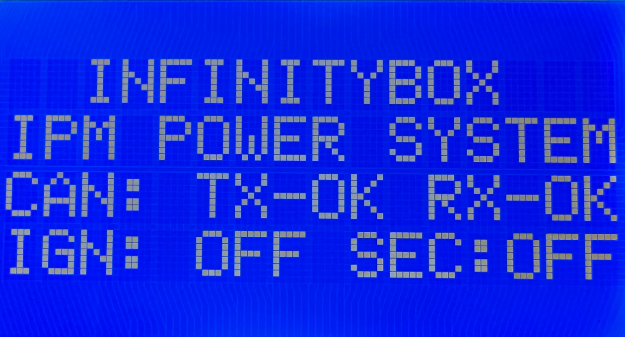
After your IPM1 kit powers up, you will see this screen on your MASTERCELL.

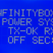
Main status screen on the MASTERCELL NGX inSIGHT display showing CAN bus status and ignition state

The main status screen on the MASTERCELL NGX inSIGHT display.

The backlight on the screen will remain on for 5 to 10 seconds then will turn off to reduce power drawn from the battery.  To return to this screen at any time, you can press and release the HOME button.

This screen gives you several important pieces of information about your Infinitybox system.  First, it tells you the status of the CAN network.  Second, it tells you the state of ignition.  Lastly, it tells you the state of security.

CAN Status

Your Infinitybox system is connected together using a J1939 CAN network.  This is a simple 2-wire system that connects your MASTERCELL to your POWERCELLs, to your inMOTION NGX cells, to your inVIEW and to any other devices connected in your car.  At a high-level, the main screen shows you the status of the CAN network.  It shows the status of the transmit circuit (TX) and the receive circuit (RX).  You will see OK for both TX and RX when the system is communicating correctly.  If you see ERR for either TX or RX, you should check your CAN cables to make sure they are connected correctly.  You should also make sure that you have the terminator resistor that came with your IPM1 kit correctly plugged into your system.  Check your IPM1 manual for more details on the termination resistor.  If you are seeing ERR for either TX and RX, contact our technical support team by clicking this link.

Ignition State

The next important thing that the main screen displays is the state of ignition.  When the ignition is on, you will see IGN: ON.  When the ignition is off, you will see IGN: OFF.  This monitors the ignition from either the switched ignition input, the one-button start input or ignition control from inTOUCH.  Specific functions in the system can be controlled with ignition.  The most common example is turn signals.  Out of the box, the system is set so that your turn signal inputs will only work when the ignition is on.  Using our inCODE NGX tool you can set other functions to be dependent on the state of ignition.  Check out the inCODE NGX details to learn more.

Security State

The last important piece of information on the main screen is the state of security.  You will see SEC: OFF when security is disabled and SEC: ON when security is enabled.  Security can be enabled and disabled from the inLINK Key Fobs and from the inTOUCH feature on inLINK.  Out of the box, the system blocks the ignition, starter and fuel pump when security is enabled.  This is a very powerful immobilizer for your car that is built into your IPM1 kit with inLINK NGX.  Using the inCODE NGX software tool, you can set other functions in the Infinitybox system to be disabled when security is enabled.  The main screen gives you a quick and simple way to check whether security is on or off.

Summary

The main screen on the inSIGHT LCD display on the MASTERCELL NGX gives you a quick snapshot of the health of the network, the state of ignition and the state of security.  Keep watching our blog for more details of the menus and functions on inSIGHT in our Next Generation System.

You can download the entire MASTERCELL NGX inSIGHT document by clicking this link.  This includes all the features and functions.

Give us a call at (847) 232-1991 or contact us here if you have any questions.

Harness Connectors

Our Infinitybox 10 and 20-Circuit Kits, plus our Express Racing Kits come with universal harnesses that connect to our MASTERCELLs, POWERCELLs and inMOTION Cells.  We chose the Aptiv family of connector systems for all of our harnesses.  They are cost effective, they are easy to work with, they don’t require expensive tools and they are easy to get through distributors.  Most importantly, they are proven in the field.

Sometimes customers make changes to their harnesses.  Sometimes they damage them and need to repair them.  Sometimes a customer just wants to build their own custom harnesses using the right connectors for the job.  We get asked a lot about the part numbers for these connectors so we just put them up in our Resources Section.  There is a new heading called Connector Components.  That has a complete bill of material for all of the harness connectors used in our system.  You can also get these documents at these links below.

Here is the document for the MASTERCELL.

Here is the document for the POWERCELL.

Here is the document for the inMOTION Cell.

We also get asked where you can buy these harness connectors.  You can get them from many different sources.  We prefer Mouser or Waytek Wire.

Give our technical support team a call if you have any questions about how to work with these connector parts.

CAN Cable

The CAN cable is the main backbone of the Infinitybox Multiplex System.  It takes the commands from the MASTERCELL and routes them to the peripheral cells, like POWERCELLs and inMOTION cells, in a system.  We get a lot of questions about this cable and how to work with it so we put this post together to answer these questions.

One of the first questions that we get is what does CAN mean?  CAN stands for Controller Area Network.  This is an automotive standard created to let different electronic systems talk together.  It was originally developed by Bosch in 1983 so it’s been around for a while.  You can read more about CAN at this link.

There area many different CAN protocols.  When a company says they communicate on CAN, that is the equivalent of saying you speak English.  English spoken in the Bronx sounds like someone speaking with a South-Side Chicago accent.  Both use the same basic works but one may not completely understand the other because of inflections and local slang.  The Infinitybox system uses a proprietary version of CAN 2.0b.  We take this standard protocol and all extra data to get more functionality out of the system.  We also have versions of our hardware that communicate on J1939, which is the commercial vehicle CAN standard.

Inside our CAN cable, there are two main wire: CAN High and CAN Low.  These send the commands between the different cells in an Infinitybox system. Additionally, we run a power and ground wire to provide voltage to the MASTERCELL.  The POWERCELLs have the ability to put out voltage through the CAN connector.  There is a very important addendum that we include with our 20-Circuit Harness kits that talks about power and ground in the CAN cables.  Please check out this link when you’re installing your kit.

A lot of guys ask where they can put their different cells on the 3-way cable that comes with the 20-Circuit Kit.  On very long CAN cables, over 30 feet, you need to have the MASTERCELL on one of the cable and the POWERCELL with the terminator resistor on the other end.  This has to do with proper impedance matching of the CAN High and CAN Low lines in the cable.  For most aftermarket installs, where the CAN cable length is under 30 feet, you can put the MASTERCELL anywhere on the CAN cable.

A lot of guys also ask about the length of the CAN cable.  We include a standard CAN cable length in the 10-Circuit and 20-Circuit Harness Kits.  This length was derived from a few years of learning from our customers and how they place cells in their cars and trucks.  We also have options when you order your kits to build custom CAN cable lengths.  You can call our sales team about this.  At the same time, there is nothing keeping you from extending or shortening your CAN cable in the system.  You can do this a few ways.

The first option is to cut the cable and splice in a new length of wire or cut out a length of wire.  There is nothing wrong with this and this is a completely acceptable way to do it.  The wire that we use is 22-AWG TXL wire.  You can buy this wire from a few sources.  We get ours from Waytek Wire and you can buy it in reasonable lengths.  This link will take you to the 22-AWG TXL section of their website.  The colors that we use in our standard CAN cables are black, green, blue and red.

It is very important that you do not cross the wires in the CAN cable.  When you’re reconnecting the connector, make sure that the wires go back where they came from.

If you’re going to splice the cables, we recommend a good butt splice connector and heat shrink.  This link will take you to a good 22-AWG butt splice from Waytek.  An 1/8″ piece of heat shrink over this will keep it protected and insulated.  Here’s a link to heat shrink.  The key to a good splice is a good crimp on the butt splice connector.  The right tool will guarantee a good job and isn’t very expensive.  Here’s a good tool for the crimp.

While a splice is completely acceptable, some guys don’t wan them in their wiring harness.  We get that.  You can create your own custom cable lengths and crimp the terminal right on the end of your wire to connect into the connector.  The connector system used for our CAN cables is very easy to work with and requires no special tools.  This picture shows you all of the parts that go into the CAN connector.

Imaging showing the different components of the Infinitybox CAN connector

Imaging showing the different components of the Infinitybox CAN connector

The yellow part is called the strain relief.  It helps to route the wires out of the connector.  The green part is the seal.  Please note that in some newer systems, the cable seals are black.  It makes the connection between the connector and the mating port on the MASTERCELL or POWERCELL water tight.  The grey part is called the connector.  It holds the terminals from the harness.  The last part is the retainer.  This is the clear clip on the front end of the connector.

The terminals that are used in this harness are made by Aptiv.  Their part number for the terminal is 15435885 and it can be sourced easily from Mouser.  This link will take you there.  This link will take you to a good quality crimp tool for these terminals.

You can cut your CAN cable to length and crimp the terminals onto the wires.  These instructions will show you how to dissemble the connector to plug these terminals into the connector.

First, get a small screw driver and gently pry up on the strain relief clips on the strain relief.  This part opens up like a clam shell.  Next, remove the Retainer from the connector.  Use a small screw driver or your fingernail to pry up on the short sides of the strain relief where it clips on to the grey connector.  Once that is done, you can gently pry up on the terminal retention tabs on the grey connector.  These hold the terminals into the connector.  When you lift them, you can pull the wire with the terminal out through the strain relief.

Reassembly of the connector is just as easy.  Crimp the terminals onto the wires and get ready to put it back together.  Just make sure that you put the right wires back into the right cavities in the connector.  The cavities area marked with an identification number on the inside of the strain relief.  Here’s how the wires should go back in.

5- Black

6- Green

7- Blue

8- Red

Make sure that the terminals are pushed to the front edge of the grey connector.  Once you have all of them in, you can snap the clear retainer back onto the grey connector.  Then close the strain relief using the strain relief clips to hold it closed.

Give our team a call if you have additional questions about working with our CAN cable or the connector components.  You can contact us directly by clicking this link.