
Posts

MASTERCELL NGX Switch States

The Switch States screen on your MASTERCELL NGX is one of the most powerful diagnostic tools in your Infinitybox IPM1 Kit. It gives you a real-time view of every switch input on your MASTERCELL NGX, so you can confirm that your switches are wired correctly and quickly track down problems. This blog post is part of our series on the diagnostic functions built into the inSIGHT screen. We introduced this screen in our overview of the MASTERCELL NGX main menu. In this post, we take a deeper look at how to read and use the Switch States screen.

Please note that this blog post covers the MASTERCELL NGX in our Next Generation IPM1 Kit. These inSIGHT diagnostic tools are specific to our Next Generation hardware. If you have our Legacy 3-Cell Kit or 20-Circuit Kit, search through our blog archives for the diagnostic tools that came with those systems.

How to Read the Switch States Screen

To get to the Switch States screen, press the HOME button on your MASTERCELL NGX to bring up the main menu, use the SCROLL UP and SCROLL DOWN buttons to move the cursor to Switch States and press SELECT. When the screen opens, you will see a series of digits arranged across four rows.

Each digit represents one switch input on your MASTERCELL NGX. The rule is simple. A 0 means that input is off. A 1 means that input is on.
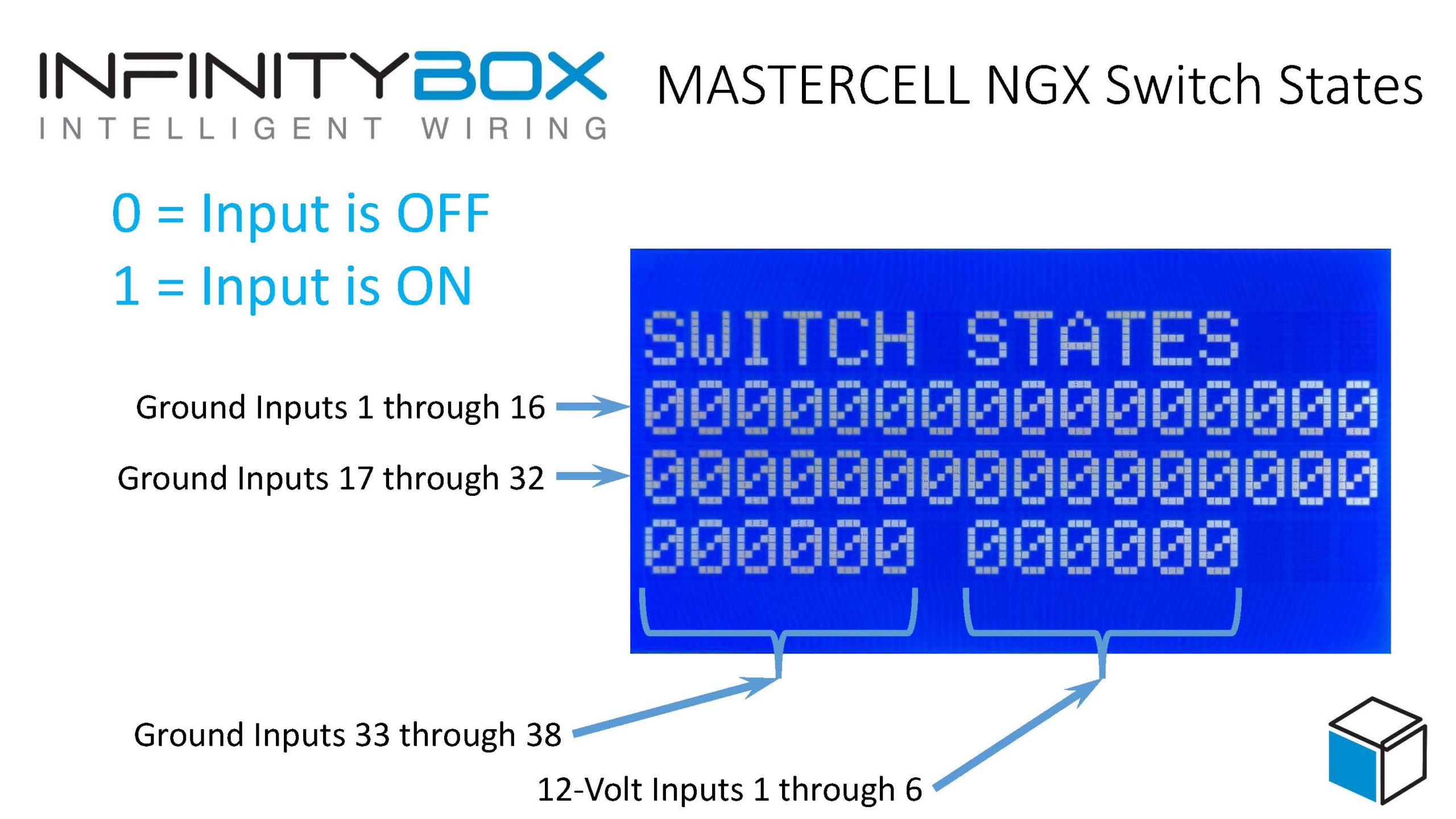
Labeled MASTERCELL NGX Switch States diagram identifying ground inputs 1 through 38 and 12-volt inputs 1 through 6 on the inSIGHT display.

MASTERCELL NGX Switch States, with callouts identifying each row of inputs and the 0 = OFF, 1 = ON legend.

The MASTERCELL NGX has 38 ground-switched inputs and 6 high-side switched inputs. The digits are laid out so that you can find any input quickly:

  • The top row shows ground-switched inputs 1 through 16.
  • The next row shows ground-switched inputs 17 through 32.
  • The bottom row shows ground-switched inputs 33 through 38 on the left.
  • After a gap, the right side of the bottom row shows the 6 high-side switched inputs, 1 through 6.

A quick note on terminology. We label the high-side switched inputs as 12-volt inputs on the screen and on your configuration sheet. Our customers use the terms “high-side switched input” and “12-volt input” interchangeably. They mean the same thing: an input that turns on when it sees 12 volts, rather than a ground. We will use 12-volt inputs through the rest of this post to match what you see on your screen.

When you are in the Switch States mode, the backlight on the inSIGHT screen will remain on.  When you are done monitoring the Switch States, you can press and release the HOME button to get back to normal operation.

Ground-Switched and 12-Volt Inputs

The MASTERCELL NGX reads two kinds of switch inputs, and the Switch States screen shows you both.

A ground-switched input turns on when it is connected to ground. This is how most of the switches in your car work with our Infinitybox system. When you flip a headlight switch, you connect the MASTERCELL NGX input to ground and the input turns on.

A 12-volt input turns on when it sees 12 volts. These are useful for connecting to devices that put out a 12-volt signal, like the fuel pump or cooling fan trigger from an EFI system. With our legacy MASTERCELL, you needed an external inVERT Mini to flip a 12-volt signal into a ground before the MASTERCELL could read it. The MASTERCELL NGX reads these 12-volt signals directly, so the inVERT Mini is no longer needed for these inputs. The Switch States screen shows you the state of both your ground-switched and 12-volt inputs in one place.

Watching the Screen in Real Time

The real power of the Switch States screen is that it updates live. As a switch turns on or off, you will see its digit change on the screen. There can be a lag of up to one second between flipping a switch and seeing the digit change, so give it a moment.

When all of your switches are off, every digit on the screen reads 0.
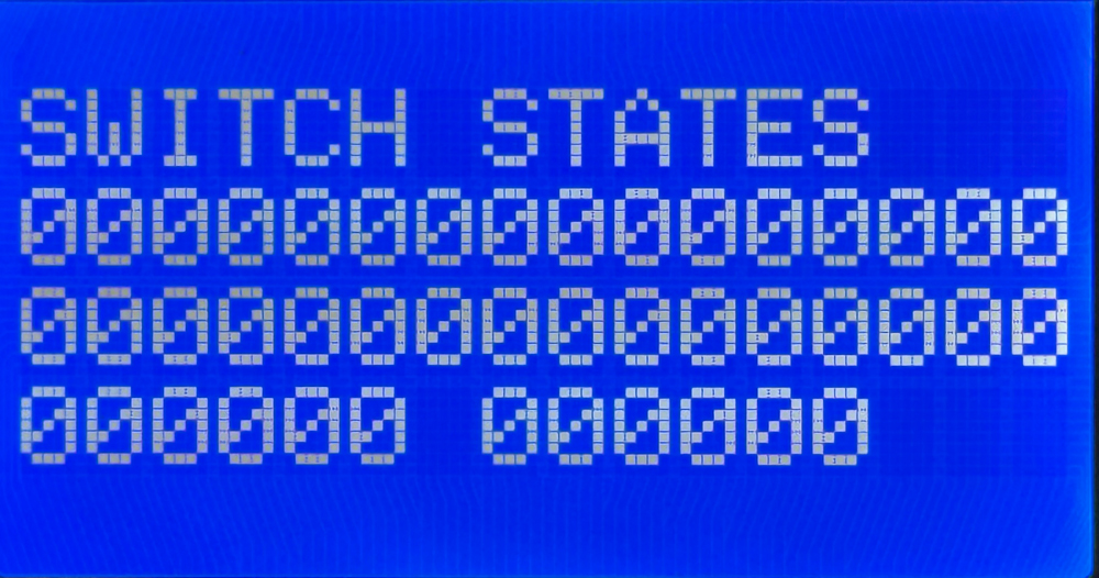
MASTERCELL NGX Switch States screen showing all inputs off, with every digit reading 0.

The Switch States screen with all inputs off. Every digit reads 0.

Now turn on one switch. In this example, we turned on the switch wired to ground-switched input 5. Watch the fifth digit in the top row. It changes from a 0 to a 1, while every other digit stays at 0.
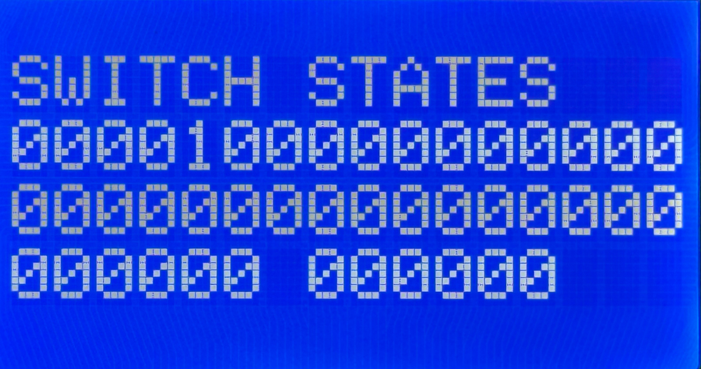
MASTERCELL NGX Switch States screen showing one ground input turned on, with a single digit reading 1.

The Switch States screen with one input on. The digit for that input changes from 0 to 1.

To know which function each numbered input controls, refer to your configuration sheet. The configuration sheet is the single source of truth for which switch connects to which input on your MASTERCELL NGX. For example, on the standard front-engine configuration, input 5 is your headlights and input 6 is your parking lights. You can see an example of the standard front-engine configuration sheet by clicking this link. Always check the configuration sheet that came with your kit, since your assignments may be different if you have a custom configuration.

Wire and Test Your Switches Before Connecting Your Loads

One of the most useful things about the Switch States screen is that it lets you wire and test every switch in your car without connecting anything to a POWERCELL.

Because the MASTERCELL NGX reads your inputs directly, you can work through your entire car one switch at a time. Wire a switch, flip it, and watch the screen confirm that the MASTERCELL NGX sees it turn on and off. You can verify your entire switch harness is correct before you ever power up a load. This lets you break your wiring project into smaller, more manageable steps and confirm each one as you go.

Track Down Problems with Switch States

The Switch States screen is also a powerful diagnostic tool when something in your car is not working the way you expect.

A question we hear often is, “Why are my parking lights on?” The Switch States screen answers this quickly. Open the screen and look at the digit for your parking light input. If that digit reads 1 when the parking light switch is off, then the MASTERCELL NGX is seeing that input turn on for some reason.

In most cases, this points to one of two things. Either the switch is wired incorrectly, or the input wire is shorted to ground somewhere in your car. Because a ground-switched input turns on when it sees ground, a wire that is accidentally pinched, chafed or shorted to ground will turn that input on just as if you had flipped the switch. The Switch States screen lets you see exactly what the MASTERCELL NGX sees, so you can focus your troubleshooting on the input that is misbehaving instead of guessing.

Summary

The Switch States screen on the MASTERCELL NGX inSIGHT display gives you a real-time, at-a-glance view of every ground-switched and 12-volt input on your system. Use it to wire and test your switches without a POWERCELL, to confirm your harness is correct as you build, and to track down shorts and wiring mistakes when something is not working. Paired with your configuration sheet, it is one of the fastest ways to understand and troubleshoot your Infinitybox system.

You can download a PDF copy of the MASTERCELL NGX Switch States diagram by clicking this link.

Keep watching our blog for more details on the menus and diagnostic functions on the inSIGHT screen. If you have any questions, give us a call at (847) 232-1991 or contact us here.

NGX Configuration Sheet- POWERCELL Outputs

We have completely re-engineered our Infinitybox system to bring the latest in wiring and body control technology to anyone wiring a hot rod, street rod, resto-mod, kit car, race car or Pro-Touring build.  We have also re-engineered the NGX configuration sheet for this system.  This new configuration sheet format makes it easier to read, gives more detail and gives all of the wire colors needed to connect to your switches and your accessories in your car or truck.  This is the standard configuration that comes loaded on all new IPM1 kits.  With our inCODE NGX programming tool, you can modify this configuration to meet the needs of your unique project.

This link will take you to the Front Engine configuration for our IPM1 kit.  Watch the resources section of our website for other setups including the Rear Engine configuration.  This blog post will walk through the details for the POWERCELL output assignments and the outputs on the MASTERCELL NGX.  Watch out blog for details on the inMOTION NGX inputs and outputs.

To start, the configuration sheet is broken down into the different cells in the Infinitybox NGX system.  This includes the front & rear POWERCELLs and the different inMOTION NGX cells for the doors (driver, passenger, driver rear & passenger rear).  Our IPM1 kit comes standard with one MASTERCELL NGX and two of our POWERCELL NGXs.  You can add as many inMOTION NGX door modules as you need for your car or truck.  Most customers will add 2 or 4 inMOTION MGX modules to their system as accessories depending on if they are working on a 2 or 4 door car.  Since the MASTERCELL NGX has low-current outputs to drive indicators on the dash, we added a page that details the wiring for these.  Lastly, we added pages that detail all the wires in the MASTERCELL A & B connector harnesses.

For the front & rear POWERCELL pages, we’ve reorganized the columns to make this easier to read.  The first column lists the function assigned to each POWERCELL output.  This includes things like turn signals, ignition, starter solenoid, lights, cooling fans and fuel pumps.  Any output that is labeled as OPEN is an auxiliary.  There is no set function assigned to the output.  Its corresponding input will turn it on and off.

The next column gives the address of the POWERCELL.  By default, the front POWERCELL is addressed as 1 and the rear POWERCELL is addressed as 2.

The next column lists the POWERCELL output by number for the function.  There are 10 outputs on a POWERCELL and they are listed in numerical order.  Some functions list multiple outputs.  Examples include the 4-ways and the One-Button Start.  In these cases, the function uses two different outputs.  The 4-ways use the left and right turn signal outputs.  The One-Button Start function uses the outputs for both the ignition and starter.

The next column gives you the POWERCELL output connector that the output is connected to.  The manual for your IPM1 kit has a diagram that identifies the A & B output connectors on the POWERCELL.  Please pay attention to this diagram carefully.  The A & B connectors are interchangeable on the POWERCELL.

The next column defines the “personality” assigned to the POWERCELL output and its corresponding input.  The personality is how the output behaves when it is turned on.  The most basic and common personality is “track”.  Outputs assigned the track personality turn on when the input is turned on and turn off when the input is turned off.  The input tracks the state of its input.  You can learn more about the other available personalities by clicking this link.

The next column lists the wire color for each output on the POWERCELL output harness.  Please note that the output harness colors for the outputs are the same for the front and rear POWERCELLs.  Pay attention to the POWERCELL address to make sure you are connecting to the right output.

The last three columns tell you the details for the MASTERCELL inputs that are controlling each POWERCELL output.  The input number, the MASTERCELL connector (A or B) and the wire color are listed.

After the POWERCELL details, the next page details the low-current outputs on the MASTERCELL NGX.  These outputs give you easy access to low-current outputs to drive indicators on your dash.  There are 8 of these outputs.  The first 4 are assigned to the left-turn signal indicator, the right-turn signal indicator, the high-beam indicator and the illumination for your gauges.  The next 4 are auxiliary outputs and can be set up as an advanced feature of the MASTERCELL NGX.  Contact our tech support team for details.

Watch the blog for more details on our new configuration sheet format and the details for the inMOTION NGX.  Click here to contact our tech support team with any questions.


Configuration Sheet

The Configuration Sheet is your road map to wiring the car with the Infinitybox 20-Circuit Kit.  It it included in the box and tells you the wire colors that connect to your switches and to your switched outputs.  This is a really important document so let’s spend a few minutes reviewing it.

All of the MASTERCELL input wires and POWERCELL output wires are color coded.  The same is true for the inMOTION output harnesses.  You are going to use the Configuration Sheet to pair these input and output wires to their switches and the outputs.

Depending on the kit that you ordered and the accessories that you have, your configuration sheet is going to be unique to your system.  Likewise, you’ll have a configuration sheet that is specific to you if we did custom programming for your system.  We also have different configuration sheets for where the engine is located in the car.  The Front-Engine configuration is our most common and is probably the most self-explanatory.  This is used for cars where the engine is in the front of the car.  The outputs for the ignition and starter are on the front POWERCELL.

If you are building a mid-engine or rear-engine car, you’d use the Rear-Engine configuration.  The outputs for the ignition and starter are on the rear POWERCELL.

We also have specific configurations for component cars made by Factory Five.  These include kits specifically configured for the Hot Rod, the GTM and the 818.  These are based on things that we have learned from hundreds of systems that we sold into guys building these cars.  If you’re building the MK4 Roadster or the Type 65 Coupe, you’d use the standard Front-Engine configuration.

This link will take you to the different configuration sheets for our Infinitybox system.

If you have lost your configuration sheet and need help locating the correct one, click here to contact our team for support.

Let’s take a look at an example.  This picture from a configuration sheet showing the details for the Headlights.  Click on this image to blow it up to see the detail.

Example of headlight wiring details from the Infinitybox configuration sheet

Example of headlight wiring details from the Infinitybox configuration sheet

The first column is Function.  This describes what is being controlled.  You’ll see that there are rows for your ignition, starter solenoid, head lights, parking lights, high-beams, horn, cooling fan, turn signals, 4-ways and brake lights.  There are also rows that marked as OPEN.  These are generic and can be used for any other accessory that you have in your car.

The next column is Switch Input.  This is the number that we use to identify the MASTERCELL inputs.  There are 48 inputs on a MASTERCELL.  Please note that the input number does not line up with the cavity marking on the input connectors.  Click on this link to get a document that connects the MASTERCELL input number to the cavity marking on the connector.  The MASTERCELL input wires are going to connect to the switches in your car.  We’ll talk about that in a later post.

The next column is MASTERCELL Connector.  There are two input connectors for a MASTERCELL, each has 24 inputs.  The majority of your inputs will be on the A connector which plugs in the socket above the MASTERCELL screen.  For systems with accessories like inMOTION and additional POWERCELLs, you will be using the B connector which is located below the MASTERCELL screen.  Some kits do not come with this MASTERCELL B harness.

The next column is POWERCELL Address.  This tells you which POWERCELL has the output that will turn on with that input.  In the case of our headlight example, the POWERCELL address is 1.  This means that the headlight output is on the front POWERCELL.  You will see that there are some rows with POWERCELL address that say 1:2.  This means that outputs on both POWERCELL 1 and POWERCELL 2 will turn on with this input.  Examples include parking lights, turn signals and 4-ways.  This link will show you how to set your POWERCELL addresses.

The next column is POWERCELL Connector.  Just like the MASTERCELL, there is an A & B output connector on the POWERCELLs.  In the case of our headlight example, the headlight output is on the B POWERCELL connector.  Your manual will show you which output harness plugs into which socket on the POWERCELL.

Next you get the Personality column.  This describes how the output will act when the input is turned on.  This separate blog post will get you more information on output personalities.  Click here to see it.  In the case of the headlight example, the output will track the input and it will soft-start.

Next you get the POWERCELL Output column.  This describes the number of the output on the POWERCELL that is turned on with the input on that row.  For our headlights, that is output number 5.

The last two columns are the most important and most practical.  Ignoring everything to the left, these two columns tell you the MASTERCELL input wire color and the POWERCELL output wire color.  For the headlights, you are going to connect the White wire with the Green tracer to the headlight switch.  You are going then take the White wire from the POWERCELL and connect that to your headlights.  When you turn on the headlight switch, the White-Green wire will get grounded by the switch.  The MASTERCELL sees this input turn.  It sends a command to the POWERCELL to turn on the headlight output.  This is the white wire.

This is one of the areas where our Infinitybox system is dramatically different from a traditional wiring harness.  Your switches connect to the MASTERCELL.  Your lights, fans, pumps, ECU’s, starter solenoid and other outputs connect to the POWERCELL.

There is a video on our YouTube channel that goes through the configuration sheet in more detail.  You can catch this video below.

Please don’t hesitate to reach out to our team with questions about the configuration sheet and how to read it.