Posts

How to Configure inMOTION NGX Door Modules with the MASTERCELL NGX

Table of Contents

What Changed

If you purchased your inMOTION NGX modules before April 1st, 2026, they came preconfigured for a specific door position. You ordered a Driver Front module, a Passenger Front module and so on. Each one was programmed before it shipped.

Starting April 1st, 2026, every inMOTION NGX ships as a universal module. Instead of ordering a door-specific part number, you configure inMOTION NGX modules yourself using the MASTERCELL NGX. This is a one-time setup that takes less than a minute per module. Once configured, the module operates at its assigned door position. You can reconfigure it at any time by running this process again.

This change means you no longer need to worry about ordering the wrong module for a specific door. Every inMOTION NGX in your kit is identical until you tell it where it lives.

You need MASTERCELL NGX software revision 1.4 or higher to use this feature.  You can learn how to check your MASTERCELL NGX software version at this blog post.  

Before You Start

Before you configure inMOTION NGX modules, make sure the following are done:

  • Your inMOTION NGX modules are mounted in their doors (Step 1 in the installation manual).
  • Power and ground are connected to each module (Step 2 in the installation manual).
  • The CAN cables are spliced and connected between the inMOTION NGX modules and your IPM1 CAN network (Step 3 in the installation manual).

You will configure each module one at a time. The MASTERCELL NGX needs to see exactly one inMOTION NGX on the CAN network during this process. That means you will disconnect all but one module, configure it, then move to the next.

inMOTION NGX Door Positions

Each inMOTION NGX must be assigned to one of four positions. The position determines which CAN address the module uses and which commands it listens to on the network.

inMOTION NGX Name Location in Vehicle CAN Address
Driver Front Driver Front Door 3
Passenger Front Passenger Front Door 4
Driver Rear Driver Rear Door 5
Passenger Rear Passenger Rear Door 6

By default, all inMOTION NGX modules ship configured as Driver Front. If you are installing a 2-door vehicle, you only need a Driver Front and a Passenger Front module. For a 4-door vehicle, you will configure all four positions.

Step-by-Step: Configure inMOTION NGX

STEP 1. Make sure only one inMOTION NGX is connected to the CAN network. Disconnect the CAN wires from all other inMOTION NGX modules. The module that remains connected is the one you are about to configure.

STEP 2. Navigate to the MASTERCELL NGX main menu using the inSIGHT display. Use the UP/DOWN buttons to scroll to inMOTION and press SELECT.

MASTERCELL NGX inSIGHT display showing the main menu with the inMOTION option selected

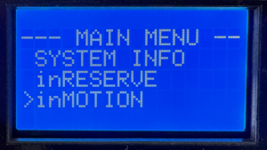
Select inMOTION from the MASTERCELL NGX main menu to begin configuration.

STEP 3. The inSIGHT display shows the inMOTION CONFIG screen. The MASTERCELL NGX scans the CAN network looking for connected inMOTION NGX modules. When it detects exactly one module, the screen reads “Connect only 1 inMOTION to CAN” with “SELECT to go” on the bottom line. Press SELECT to proceed.

MASTERCELL NGX inSIGHT display showing inMOTION CONFIG connection check screen with SELECT to go prompt

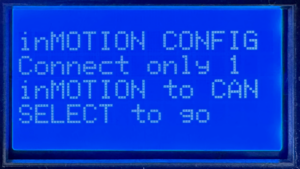
The MASTERCELL NGX confirms it sees exactly one inMOTION NGX on the CAN network.

If the screen displays “Waiting…” instead, the MASTERCELL NGX has not detected any inMOTION NGX modules. Verify that the module has power, is properly grounded and that the CAN wires are correctly spliced to the network.

If the screen shows that more than one inMOTION NGX was found, it will block you from proceeding. Disconnect the extra modules so only one remains on the CAN network, then try again.

STEP 4. The inSIGHT display shows a list of door positions. Use the UP/DOWN buttons to select the position you want to assign to this module: Driver Front, Passenger Front, Driver Rear or Passenger Rear. Press SELECT to confirm your choice.

MASTERCELL NGX inSIGHT display showing the Select Position screen with Driver Front, Passenger Front and Driver Rear options

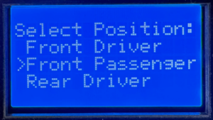
Use UP/DOWN to choose the door position for this inMOTION NGX module.

STEP 5. A confirmation screen appears showing the position you selected. Press SELECT to confirm or HOME to cancel and go back to the position list. Once you confirm, the MASTERCELL NGX sends the configuration commands over CAN. This takes a few seconds while it writes the new settings and verifies the module responds at its new address.

MASTERCELL NGX inSIGHT display showing configuration confirmation screen for Passenger Front with SELECT to Confirm and HOME to Cancel options

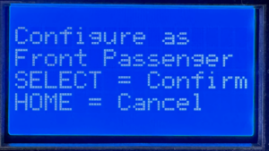
Confirm your selection. Press SELECT to write the configuration or HOME to go back.

STEP 6. When the configuration is complete, the screen displays the new position assignment with a “Success!” message. Press HOME to return to the menu.

MASTERCELL NGX inSIGHT display showing inMOTION CONFIG Success screen with Device is now Passenger Front confirmation

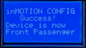
Configuration complete. The inMOTION NGX is now assigned to its door position.

STEP 7. Repeat this process for each inMOTION NGX module in your system. Disconnect the module you just configured from the CAN network, connect the next one and run through the steps again. Continue until every module is assigned to its door position.

Once all modules are configured, reconnect all of them to the CAN network. Navigate to System Inventory on the MASTERCELL NGX to verify that every inMOTION NGX appears at its correct position.

Troubleshooting

The screen says “Waiting…” and never finds my module.
Check that the inMOTION NGX has power on both red 14-AWG wires and is properly grounded on both black 14-AWG wires. Verify that the green and yellow CAN wires are spliced correctly to the IPM1 CAN cable. Make sure the CAN wires are not reversed — green to green (CAN LO) and yellow to yellow (CAN HI).

The screen says it found more than one module.
Only one inMOTION NGX can be on the CAN network during configuration. Disconnect the CAN wires from all other inMOTION NGX modules and try again.

I configured a module to the wrong position.
Run the process again. Connect only that module to the CAN network and assign it to the correct position. The new configuration overwrites the previous one.

Download the Full Manual

This post covers the configuration process for the inMOTION NGX. For complete installation instructions including mounting, power and ground, CAN wiring, output wiring and switch wiring, download the full inMOTION NGX Installation Manual.

Questions?

If you have any questions about how to configure inMOTION NGX modules or anything else about your Infinitybox system, our technical support team is here to help. Give us a call at (847) 232-1991 or fill out our contact form and we will get back to you.

Picture of the Holley Sniper EFI System

How to Wire the Holley Sniper EFI with the Infinitybox IPM1 Kit

Until recently, electronic fuel injection was completely out of the hands of your typical automotive enthusiast. Over the past years, many different companies have introduced powerful and elegant systems to bring the benefits of EFI to anyone. Holley’s Sniper EFI system is one of the most popular. It is a cost-effective throttle body EFI system that can handle up to 650 horsepower and can be tuned without a laptop. Wiring the Holley Sniper EFI system is a breeze with our Infinitybox Intelligent Power Management Kit, the IPM1. This blog post will take you through the details.

Note: This post covers wiring the Holley Sniper EFI with our current IPM1 Kit and the MASTERCELL NGX. If you are wiring the Sniper with our Legacy 20-Circuit Kit, click here to see our original Holley Sniper EFI wiring guide.

Table of Contents

What Changed: IPM1 Kit vs. the Legacy 20-Circuit Kit

If you are familiar with our earlier blog posts, you may have seen our original guide for wiring the Holley Sniper EFI with our Legacy 20-Circuit Kit. We have replaced that kit with the IPM1 Kit, which includes our new MASTERCELL NGX. There are some important differences that simplify how you wire the Sniper EFI.

The biggest change is that the MASTERCELL NGX has both ground-switched and high-side switched inputs. Our Legacy 20-Circuit Kit only had ground-switched inputs on the MASTERCELL. If a trigger from an aftermarket system like the Sniper sent a 12-volt signal, you had to install an inVERT Mini inline to flip that signal to a ground trigger. With the MASTERCELL NGX, high-side switched inputs are built in. The fuel pump trigger from the Sniper EFI is a 12-volt signal. You can now connect it directly to a high-side input on the MASTERCELL NGX without needing an inVERT Mini. This saves you a component and simplifies your wiring.

The MASTERCELL NGX also includes dedicated low-current indicator outputs that can directly drive dash indicators like your turn signal indicators, high-beam indicator, and gauge illumination. On top of that, the MASTERCELL NGX is fully programmable and configurable by the customer.

Wiring the Holley Sniper EFI System with your Infinitybox IPM1 Kit

Our Infinitybox system can interface with any electronic fuel injection system on the market. Wiring the Holley Sniper EFI is as simple as wiring their Terminator or their Dominator. Click on this link to get to the details of wiring the Holley Terminator. Click on this link to get to the details of wiring the Holley Dominator.

Before you start wiring the Holley Sniper EFI, you must thoroughly read and understand the instructions that came with your kit. This link will take you to the Holley manual. Note that this blog post is just going to cover wiring ignition power from your Infinitybox system and wiring the fuel pump and cooling fan. The Holley manual will cover the rest of the wiring details.

This diagram shows you the connections between your Holley Sniper EFI and your Infinitybox IPM1 Kit with the MASTERCELL NGX.


Wiring diagram showing how to connect the Holley Sniper EFI to the Infinitybox IPM1 Kit with the MASTERCELL NGX

Wiring diagram showing the connections between the Holley Sniper EFI and the Infinitybox IPM1 Kit with the MASTERCELL NGX, including the fuel pump trigger on a high-side input and the cooling fan trigger with a 1N4001 isolation diode.

Battery Power and Ground

First things first, you need to get battery power and ground to the Sniper. The red wire in their 7-pin connector must go directly to the positive terminal on your battery. The black wire in their 7-pin connector must go to ground. As we discuss in other blog posts, 90% of all electrical problems relate to a bad ground. Make sure that you have a solid metal-to-metal connection to your chassis with no paint, grease, powder coating, or dirt in the way.

Ignition Power to the Sniper EFI

Next, you need to bring ignition power from your POWERCELL to the pink wire on their 7-pin harness. In most Infinitybox systems, this is the light-green wire on your front POWERCELL but check your configuration to be sure. This POWERCELL output will supply battery power to the Sniper whenever you have the ignition switch on.

Wiring the Cooling Fan Trigger from the Holley Sniper EFI

Next, you need to connect the MASTERCELL NGX input for your cooling fan to the light-blue wire on the Sniper 10-pin harness. The cooling fan trigger from the Sniper is a ground-switched output. Even though the MASTERCELL NGX accepts ground-switched inputs directly, we always recommend isolating any ground-switched input from an external system like the Sniper EFI. The reason is that we do not know what the Sniper does with its trigger when it is off. It may let the trigger float or pull it up to battery voltage. Either of these conditions could cause erratic behavior on the MASTERCELL NGX input.

To isolate the input, you must install a 1N4001 diode in series between the MASTERCELL NGX input and the cooling fan trigger on the Holley harness. Install the diode with the anode facing the MASTERCELL NGX. Note that the orientation of this diode is critical. Check the diagram above for the correct orientation of the stripe on the diode.

There are several advantages to using the Infinitybox system to control the cooling fan directly off of the Sniper harness. First, you do not need to add a relay. That is built into the POWERCELL. Second, our cooling fan outputs are set to soft-start the motor. Click here to learn more about the benefits of soft-starting.

Wiring the Fuel Pump Trigger from the Holley Sniper EFI

Next, it is time to wire the fuel pump. The dark-blue wire on the 7-pin connector is the fuel pump trigger. This is a 12-volt signal from the Sniper. With the MASTERCELL NGX in your IPM1 Kit, you can connect this fuel pump trigger directly to one of the high-side switched inputs on the MASTERCELL NGX. There is no need for an inVERT Mini. The MASTERCELL NGX has the equivalent of that circuit built into its high-side inputs. This is one of the key improvements over the Legacy 20-Circuit Kit, which required an inVERT Mini inline to convert this 12-volt trigger to a ground signal.

The diagram above shows you how to connect the dark-blue fuel pump trigger wire from the Sniper directly to the high-side input on the MASTERCELL NGX.

There are several advantages to using the Infinitybox system to control the fuel pump directly from the Sniper harness. First, we can disable the fuel pump as a security measure if you have our inLINK Radio upgrade. More importantly, having the Infinitybox system control the fuel pump means that you have to run less wire in the car. The MASTERCELL NGX is located close to the EFI system. The rear POWERCELL is mounted near the fuel pump in the tank. There is no extra fuel pump wiring required to make it work.

Summary

Wiring the Holley Sniper EFI system with your Infinitybox IPM1 Kit and the MASTERCELL NGX is straightforward. The high-side switched inputs on the MASTERCELL NGX eliminate the need for an inVERT Mini on the fuel pump trigger, which simplifies your wiring. Remember to isolate the ground-switched cooling fan trigger with a 1N4001 diode to protect the MASTERCELL NGX input.

You can download a PDF of our wiring diagram by clicking this link.

Click this link to contact our team with any questions about how our Infinitybox IPM1 Kit can streamline your wiring projects.

Documentation for inMOTION NGX Modules

Our inMOTION NGX revolutionizes the way your wire your door functions in your restoration, street rod, kit car, hot rod, restomod or Pro-Touring build.  Instead of running large bundles of wires through the door hinge, we reduce that down to 4 simple wires.  inMOTION NGX is the next generation of door control modules.  In one box, you can easily wire your power locks and windows with much less wire running to the door than traditional wiring harnesses.  You simply mount the inMOTION NGX module in your door and you get local control with less wire.  You need to simply run power, ground and our two CAN wires through the hinge of the door.  This blog is going to walk through the manual and the configuration sheet for inMOTION NGX.

Since you have one inMOTION NGX module per door, you can easily scale your car or truck build by adding as many as you need.  The modules communicate with each other using a J1939 network.  That means you can easily get central locking from all the doors.  You can also control passenger windows from the driver’s door.  You get late-model conveniences in your classic car or truck.

inMOTION NGX is designed to control your power lock actuator and power window motor from inside the door.  We use special polarity reversing relays to control these features from any switch.  We also build 4 outputs into the inMOTION NGX module for local control of switch indicators, interior lights, accent lighting, puddle lights or other features.

This link will take you to the manual for our inMOTION NGX kit.  This document takes you through the process of wiring your doors with inMOTION NGX.  It describes how inMOTION NGX works, talks about how to properly mount it in your door, details wiring the switches and loads to the module and gives you a check list for each step.

There is a configuration sheet specific to inMOTION NGX.  This sheet details which input wires connect to your switches and which output wires connect to your loads.  It also shows how the different inMOTION NGX modules interact with each other and the other parts of the Infinitybox IPM1 kit.  You can download the standard configuration sheet by clicking this link.

Contact our team to learn more about the inMOTION NGX Kit, the manual and the configuration sheet.  Click here to get in touch with our team.

Wiring Russ Thompson Turn Signal System

Russ Thompson has been making high-quality turn signal assemblies for the full range of Factory Five Cars.  We have been getting a lot of requests for a wiring diagram to show you how to connect his turn-signal switch to our new Infinitybox IPM1 kit.  This blog post will get you those details.  Please note that this post details the wiring using our Next Generation System.  Please click here if you have one of our Legacy Infinitybox systems.

Russ Thompson made high-quality turn signal stalk assemblies for the Factory Five Roadster, Type 63 and the GTM.  You can learn more about his products at this link.

The new Infinitybox IPM1 kit includes the next generation of our MASTERCELL and POWERCELLs.  These products include numerous refinements and enhancements that our customers have requested.  You can learn more about the IPM1 kit at this link.  Turn signals and 4-way flashers have always been easy to wire with the Infinitybox system.  The addition of indicator outputs on the MASTERCELL NGX make this even easier.

The Infinitybox manages all the required functions for turn signals and 4-ways.  The MASTERCELL handles the patterns internally so you do not need a flasher relay.  You simply ground the inputs for the left and right turn signals to make them work.  We manage the rest for you.  The distributed architecture of the system makes running the wire through your car easy.  You have a POWERCELL output module in the front of your car and one in the rear.  Each of these POWERCELLs has outputs for turn signals.  That means that you are running the front turn signals from the front POWERCELL and the rear signals from the rear.  All of your wire is run locally.  This minimizes the total amount of wire needed in the car.

We also manage the 4-ways or hazards internally.  The MASTERCELL generates the pattern so no external flasher is required.  When you ground the input for the 4-ways, the MASTERCELL tells the front & rear POWERCELLs to flash all the turn signals together.

Wiring the turn signal switch and the hazard switch is very easy with the Infinitybox IPM1 kit.  You simply connect the left turn, right turn and 4-way inputs from the MASTERCELL to the switches in the Russ Thompson turn signal stalk.  Instead of connecting the other side of the switch to a flasher, you connect it to ground.  When you turn on a switch, that pulls the MASTERCELL input to ground, which triggers its function.  The following diagram shows how to connect the inputs to the stalk switches.

Picture of Infinitybox wiring diagram showing how to wire Russ Thompson Turn Signal Stalk

Picture of Infinitybox wiring diagram showing how to wire Russ Thompson Turn Signal Stalk

The wire colors for your MASTERCELL inputs are defined in the configuration sheet that came with your kit.  Click on this link to get to our standard front-engine configuration.

For the turn signal wires from the stalk, the black-red wire should connect to ground.  The red-white wire connects to the MASTERCELL input for your left turn signal and the red-yellow wire connects to the input for the right turn signal.

There is another great feature included with our MASTERCELL NGX.  In addition to the inputs, the MASTERCELL NGX has outputs to locally power things like indicators.  Since your MASTERCELL is located close to your switches, it is very easy to run these indicator wires to the indicator lights on your dash for your turn signals and indicators.  When the MASTERCELL is telling the POWERCELLs to flash the turn signals, it is also flashing the indicators.  See the wiring diagram above for details on wiring you dash indicators.

The last feature in the Russ Thompson kit is the button at the end of the turn signal stalk.  This is a momentary button intended to be used to control the high-beams.  With a typical wiring set up, you would need a separate relay or high-beam module to manage this.  With the Infinitybox IPM1 kit, you can control your high-beams from this momentary button internally.  Our high-beam input can be set to toggle the high-beams on and off.  See the diagram above to show how to wire this input to the switch in the Russ Thompson kit.  Both the wires for the button on the Russ Thompson harness are black.  Connect one to ground and the other to the MASTERCELL input for the high-beams.

You can also use this button to control the horn if you want.  Instead of the high-beam input, connect the horn input.  See you configuration sheet for details.

You can download a PDF version of this wiring diagram by clicking this link.

Contact our technical support team if you have any questions about wiring your Factory Five car using our Infinitybox IPM1 kit and the Russ Thompson turn signal stalk kit.

NGX Configuration Sheet- POWERCELL Outputs

We have completely re-engineered our Infinitybox system to bring the latest in wiring and body control technology to anyone wiring a hot rod, street rod, resto-mod, kit car, race car or Pro-Touring build.  We have also re-engineered the NGX configuration sheet for this system.  This new configuration sheet format makes it easier to read, gives more detail and gives all of the wire colors needed to connect to your switches and your accessories in your car or truck.  This is the standard configuration that comes loaded on all new IPM1 kits.  With our inCODE NGX programming tool, you can modify this configuration to meet the needs of your unique project.

This link will take you to the Front Engine configuration for our IPM1 kit.  Watch the resources section of our website for other setups including the Rear Engine configuration.  This blog post will walk through the details for the POWERCELL output assignments and the outputs on the MASTERCELL NGX.  Watch out blog for details on the inMOTION NGX inputs and outputs.

To start, the configuration sheet is broken down into the different cells in the Infinitybox NGX system.  This includes the front & rear POWERCELLs and the different inMOTION NGX cells for the doors (driver, passenger, driver rear & passenger rear).  Our IPM1 kit comes standard with one MASTERCELL NGX and two of our POWERCELL NGXs.  You can add as many inMOTION NGX door modules as you need for your car or truck.  Most customers will add 2 or 4 inMOTION MGX modules to their system as accessories depending on if they are working on a 2 or 4 door car.  Since the MASTERCELL NGX has low-current outputs to drive indicators on the dash, we added a page that details the wiring for these.  Lastly, we added pages that detail all the wires in the MASTERCELL A & B connector harnesses.

For the front & rear POWERCELL pages, we’ve reorganized the columns to make this easier to read.  The first column lists the function assigned to each POWERCELL output.  This includes things like turn signals, ignition, starter solenoid, lights, cooling fans and fuel pumps.  Any output that is labeled as OPEN is an auxiliary.  There is no set function assigned to the output.  Its corresponding input will turn it on and off.

The next column gives the address of the POWERCELL.  By default, the front POWERCELL is addressed as 1 and the rear POWERCELL is addressed as 2.

The next column lists the POWERCELL output by number for the function.  There are 10 outputs on a POWERCELL and they are listed in numerical order.  Some functions list multiple outputs.  Examples include the 4-ways and the One-Button Start.  In these cases, the function uses two different outputs.  The 4-ways use the left and right turn signal outputs.  The One-Button Start function uses the outputs for both the ignition and starter.

The next column gives you the POWERCELL output connector that the output is connected to.  The manual for your IPM1 kit has a diagram that identifies the A & B output connectors on the POWERCELL.  Please pay attention to this diagram carefully.  The A & B connectors are interchangeable on the POWERCELL.

The next column defines the “personality” assigned to the POWERCELL output and its corresponding input.  The personality is how the output behaves when it is turned on.  The most basic and common personality is “track”.  Outputs assigned the track personality turn on when the input is turned on and turn off when the input is turned off.  The input tracks the state of its input.  You can learn more about the other available personalities by clicking this link.

The next column lists the wire color for each output on the POWERCELL output harness.  Please note that the output harness colors for the outputs are the same for the front and rear POWERCELLs.  Pay attention to the POWERCELL address to make sure you are connecting to the right output.

The last three columns tell you the details for the MASTERCELL inputs that are controlling each POWERCELL output.  The input number, the MASTERCELL connector (A or B) and the wire color are listed.

After the POWERCELL details, the next page details the low-current outputs on the MASTERCELL NGX.  These outputs give you easy access to low-current outputs to drive indicators on your dash.  There are 8 of these outputs.  The first 4 are assigned to the left-turn signal indicator, the right-turn signal indicator, the high-beam indicator and the illumination for your gauges.  The next 4 are auxiliary outputs and can be set up as an advanced feature of the MASTERCELL NGX.  Contact our tech support team for details.

Watch the blog for more details on our new configuration sheet format and the details for the inMOTION NGX.  Click here to contact our tech support team with any questions.