 Copyright 2026 Infinitybox, LLC. All Rights Reserved.
 Wiring Dakota Digital GRFX Gauges with the IPM1 Kit
Table of Contents
- Overview
- Constant Power and Ground
- Key-On Power
- Gauge Illumination
- Turn Signal and High-Beam Indicators
- Legacy 20-Circuit Kit vs. IPM1 Kit
- Downloads and Support
Overview
Dakota Digital has been in the business of making advanced electrical products for the automotive aftermarket for a long time. Their products include gauges, lighting, cruise control systems, gear indicators, linear actuators, climate control interfaces and other automotive accessories. Their GRFX series represents the latest in their electronic dashboard technology. The GRFX system features full-color TFT displays with user-configurable layouts, themes and colors. A lot of our customers have asked about how to connect their GRFX controller box to our Infinitybox system. This blog post is going to walk you through the details of wiring Dakota Digital GRFX gauges with the IPM1 Kit featuring the MASTERCELL NGX.
This post is specific to our IPM1 Kit with the MASTERCELL NGX. If you have our legacy 20-Circuit Kit or our 3-Cell Kit, the wiring connections are different.
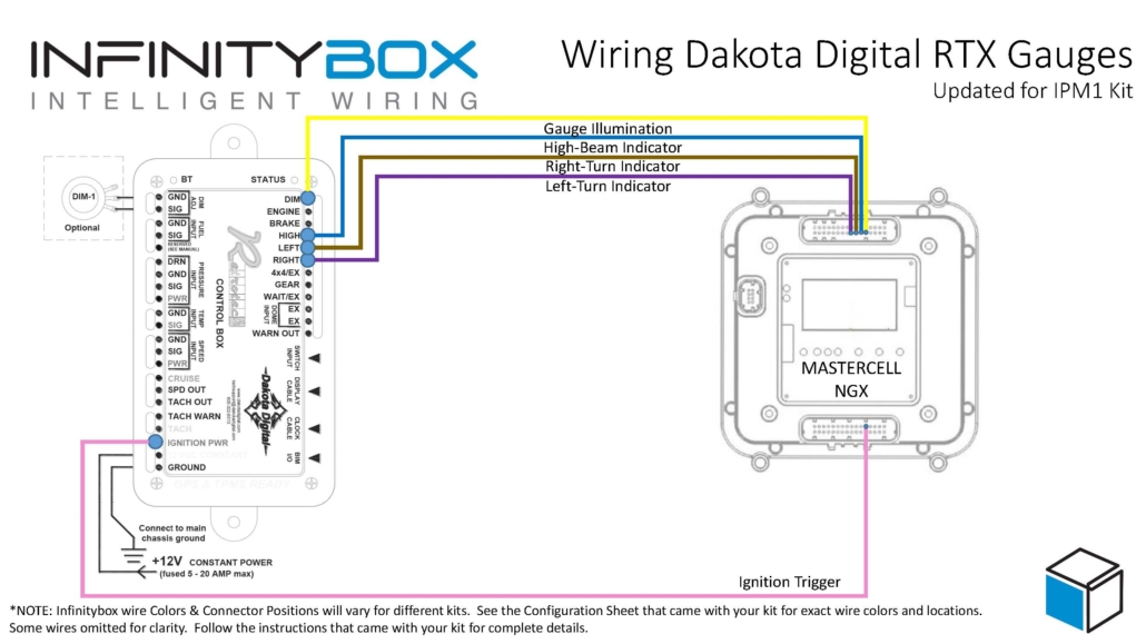
Before we go too far, this post is only going to cover wiring primary power, ground, key-on power, gauge illumination and the signals for the indicators on the dash. Their manual will cover the details for the rest of the wiring. If you are using the VHX or RTX gauges, we have separate posts covering those systems.
The big advantage of the IPM1 Kit is how the MASTERCELL NGX simplifies these connections. The MASTERCELL NGX has built-in low-current indicator outputs. In most installations, the MASTERCELL is located behind the dash — right where the Dakota Digital GRFX controller box is also located. With the IPM1 Kit, you can connect the MASTERCELL NGX indicator outputs directly to the GRFX controller without running wires back to the front POWERCELL. This is a significant wiring simplification compared to the legacy 20-Circuit Kit.
Important: The indicator outputs on the MASTERCELL NGX are limited to 1 amp each. The Dakota Digital documentation shows that the IGNITION PWR terminal on the GRFX controller draws less than 1 amp, which means it can be connected directly to a MASTERCELL NGX output. The turn signal indicators, high-beam indicator and gauge illumination outputs are designed to drive low-current loads. Do not connect anything else to these outputs that could push the total current draw over the 1-amp threshold.
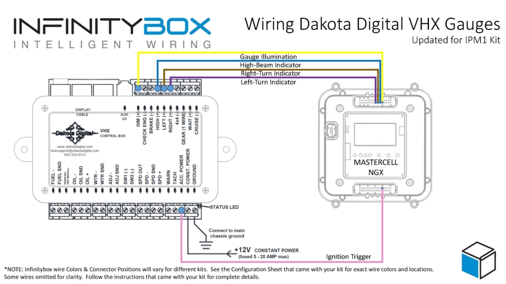
This diagram shows an overview of the connections from the MASTERCELL NGX to the GRFX controller box.
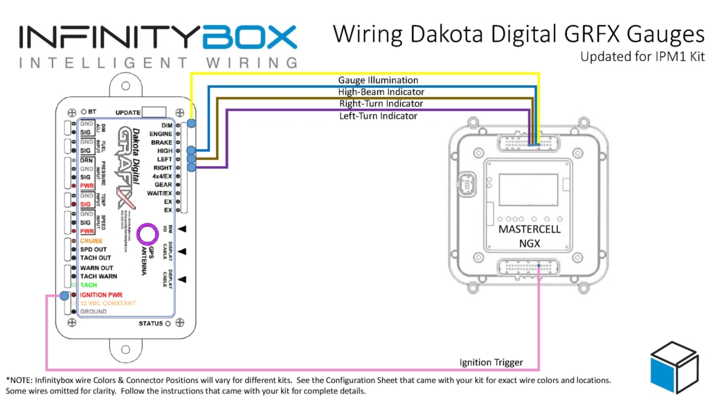
Wiring diagram showing how to wire the Dakota Digital GRFX Controller Box to the Infinitybox IPM1 Kit.
Constant Power and Ground
The GRFX controller needs constant power from the battery. Connect the 12 VDC CONSTANT terminal on their controller box directly to the positive terminal on the battery. You must fuse this wire at the battery for safety. Dakota Digital recommends a fused 5 to 20 amp circuit for this connection.
You also have to connect the GROUND terminal on their controller box to a good chassis ground connection. This must be a metal-to-metal connection that is free of paint, powder coating, dirt and debris.
Key-On Power
The GRFX controller box needs ignition or key-on power. This is what turns the gauges on when you turn the key in the car. With the IPM1 Kit, your MASTERCELL NGX has a dedicated indicator output for the ignition signal. Connect this output to the IGNITION PWR terminal on the GRFX controller box.
Since the MASTERCELL NGX is located behind the dash, this connection is short and direct. You are connecting two components that are both behind the dash. With the legacy 20-Circuit Kit, this power came from the front POWERCELL ignition output and you had to run a wire from the front of the car back to the GRFX controller behind the dash.
Check the configuration sheet that came with your IPM1 Kit to confirm the specific output assignment for your ignition indicator.
Gauge Illumination
You need to connect the gauge illumination output on the MASTERCELL NGX to the DIM(+) terminal on the GRFX controller box. This will change the display colors and brightness on the GRFX gauges when you have your parking or headlights on.
Again, this is a direct behind-the-dash connection with the IPM1 Kit. The MASTERCELL NGX indicator output for the gauge illumination connects straight to the DIM(+) terminal on the GRFX controller.
Turn Signal and High-Beam Indicators
Lastly, you need to connect the MASTERCELL NGX indicator outputs for your turn signals and high-beam to their respective terminals on the GRFX controller box. Connect the left turn signal indicator output to the LEFT(+) terminal, the right turn signal indicator output to the RIGHT(+) terminal and the high-beam indicator output to the HIGH(+) terminal.
When the MASTERCELL NGX is commanding the left turn signal, the indicator output will trigger and the left turn signal indicator will flash on the Dakota Digital GRFX display. The same applies for the right turn signal and the high-beam indicator.
These are all low-current indicator signals. The MASTERCELL NGX indicator outputs are purpose-built for this type of connection.
Legacy 20-Circuit Kit vs. IPM1 Kit
With the legacy 20-Circuit Kit, all of the signals going to the GRFX controller box came from outputs on the front POWERCELL. The ignition power, parking light dimmer, turn signals and high-beam connections all required splicing into POWERCELL output wires at the front of the car and running those wires back behind the dash to reach the GRFX controller. That meant longer wire runs and more splices.
The IPM1 Kit with the MASTERCELL NGX eliminates those long wire runs. The MASTERCELL NGX has built-in low-current indicator outputs that connect directly to the GRFX controller box. Since both the MASTERCELL NGX and the GRFX controller are located behind the dash, these connections are short and direct. You get a cleaner installation with less wiring.
The constant power and ground connections remain the same in both systems. The GRFX controller still gets its constant power directly from the battery and its ground from the chassis.
Downloads and Support
You can download a PDF of this wiring diagram by clicking this link.
Our technical support team is available to answer any questions about this blog post or any other topics about wiring your car with our Infinitybox system. Click on this link to get in touch with our team.


 Copyright 2026 Infinitybox, LLC. All Rights Reserved.
 Copyright 2026 Infinitybox, LLC. All Rights Reserved.
 Copyright 2026 Infinitybox, LLC. All Rights Reserved.