
Digital Guard Dawg iKEY
We always say that our Infinitybox system plays nicely with any other piece of automotive electronics. We have our own remote keyless entry system with inLINK and our one-button start feature is built into all of our 10 and 20-Circuit Kits. Some of our customers like to use push-button start feature and Passive Key Less Entry (PKE) system manufactured by other companies. This post will go through the details of connecting the Digital Guard Dawg iKEY system to the Infinitybox system.
Before we go any further, you must thoroughly read and completely understand the manuals that come with your Digital Guard Dawg iKEY system. In the case of this system, there are two manuals. One for the push-button start module and one for the PKE module. This blog post is only going to describe how to connect the wires that are relevant to the Infinitybox system. Carefully follow the instructions for all of the other connections to their harnesses including power and ground.
By connecting the Digital Guard Dawg iKEY to the Infinitybox system, you get all of the advantages of Infinitybox plus the PKE features of the iKEY system. The iKEY system has several outputs that are +12 volts and ground switched. The Infinitybox MASTERCELLs work on ground signals. You will need to use our inVERT Mini‘s to connect the +12 volt outputs to the MASTERCELL inputs. Failure to do so will damage the inputs on the MASTERCELL and will void your warranty. Also, you must use a diode to isolate the ground outputs on the Digital Guard Dawg iKEY from the MASTERCELL inputs. Failure to do this could result in damage to the inputs and will void your warranty. You can use a 1N4001 diode easily sourced from any electronics store. Also note that the orientation of the diode is critical. Please pay attention to this in the wiring diagrams.
Please note that the wire colors and connector locations shown in the following diagrams may not match your system exactly. We have several different configurations. Please reference the configuration sheet that came with your kit for the exact wire colors and connector locations.
The following diagram shows you how to connect the Push-Button Start module to the MASTERCELL inputs and POWERCELL outputs of your Infinitybox system.

Picture of the wiring diagram showing the Digital Guard Dawg Push Button Start Wiring with the Infinitybox System
Here are the details:
- Digital Guard Dawg has a dedicated harness with Negative Ignition Outputs designed to work with our Infinitybox system. You can use this harness to connect directly to the MASTERCELL inputs for the Ignition, Starter and Accessory. The yellow wire in their harness connects to your starter input. The green wire connects to your ignition input and their white wire connects to your accessory input.
- Connect the Black wire from the accessory harness to the neutral safety or clutch interlock switch. This is the same switch used for the neutral safety input going to the MASTERCELL. Be sure to wire in the diode to isolate the MASTERCELL input from the Push-Button Start module.
- Tap off of the brake light output on your rear POWERCELL and connect that to the Brown wire on your accessory harness.
This diagram will show you how to wire the PKE module to the Infinitybox system.
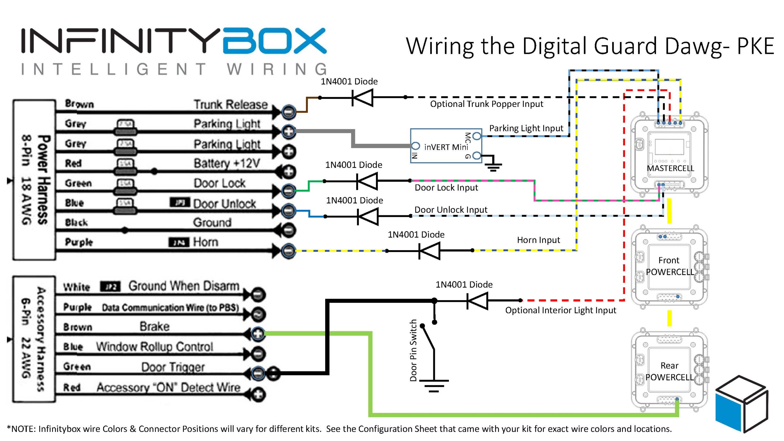
Picture of the wiring diagram showing the Digital Guard Dawg PKE Wiring with the Infinitybox System
Here are the details.
- Connect the Brown wire on the power harness through a diode to an optional input for a trunk popper. Not all of our systems may be set up for this feature. Your system may need to be updated to add this.
- Connect one of the Grey wires from the power harness to an inVERT Mini. Tap into the MASTERCELL input for the parking light and connect that to the MASTERCELL side of the inVERT Mini.
- Connect the Green and Blue wires from the power harness to the optional inputs for door lock and unlock. You need to have inMOTION for this option to work. The MASTERCELL inputs must be isolated from the PKE module by diodes as shown in the drawing.
- Connect the Purple wire from the power harness to your MASTERCELL input for the horn through a diode.
- Connect the Green wire from the accessory harness to the pin switches on your doors. This is the same switch used for the interior lights input going to the MASTERCELL. Be sure to wire in the diode to isolate the MASTERCELL input from the Push-Button Start module.
- Tap off of the brake light output on your rear POWERCELL and connect that to the Brown wire on your accessory harness.
You can download a PDF version of this wiring diagram by clicking this link.
If you follow these instructions, you can get the full functions of the Digital Guard Dawg iKEY system. You can pop your trunk and control your door locks from their system. You get PKE functionality from their remotes. You get their one-button start feature.
Click on this link to contact our technical support team with additional questions about connecting your Digital Guard Dawg iKEY system to our Infinitybox system.
 Copyright Infinitybox, LLC 2021. All Rights Reserved.


 Copyright Infinitybox, LLC 2021. All Rights Reserved.


