Wiring turn signals, 4-ways and the horn to the MASTERCELL in your Infinitybox system is very easy. Our inputs can connect to the connectors of any steering column. This blog post is going to cover the IDIDIT Mustang Steering Column wiring. Specifically, this is for their 1965 & 1966 columns.
Before you go too far, be sure to read and understand the instructions for installing your column. You can download the IDIDIT instructions for this Mustang column by clicking here. IDIDIT gives you the connector components to plug directly into the original harness in your Mustang. The difference with our Infinitybox system is that your MASTERCELL inputs are going to wire to the switches on the column. The switches on the column become triggers to the MASTERCELL. Our Infinitybox system takes care of the rest.
This diagram will show you which MASTERCELL input wires need to connect to the terminals on the IDIDIT column.
Picture of a wiring diagram showing how to wire the IDIDIT Mustang steering column to the Infinitybox MASTERCELL
Please note that this diagram does not give you the MASTERCELL input wire colors. You need to line up the function on the column to the wire color on your configuration sheet. Depending on your system and your accessories, you may have different wire colors for your inputs. Click on this link to learn more about your configuration sheet.
The connections between the Infinitybox MASTERCELL and the connector on the column are easy. Essentially, you only need to connect the inputs for your left turn signal, right turn signal and the horn. Then you need to ground two of the column wires to the chassis. That’s it.
We get a lot of questions about cooling fans and whether or not you can drive them directly from a POWERCELL output without a relay. In this post we’re going to talk about cooling fan in-rush current and show you what this looks like.
Any motor has an in-rush of current that flows through it upon start up. To keep this simple, the windings of the motor look like a short circuit until they start to turn. At start up, the current flow through the windings is high but settles down to a steady-state current level when the motor gets to its operating speed. This peak in-rush current can be 4 to 8 times the steady-state current, depending on the motor.
When you buy a typical cooling fan, the manufacturer will tell you that you need a high-current relay to switch the fan on and off. Typically these relays are 40 or 70-amps. You need to use a relay with contacts that are sized to handle the in-rush current that flows to the motor. With our Infinitybox system, we don’t use relays. We use MOSFETs designed to control inductive loads like motors. The point of this blog post is to show you what the in-rush looks like on a typical cooling fan.
We used the cooling fan in our 1979 Jeep CJ7 to get a real-life example of what this in-rush looks like. The fan has a 16″ diameter and we powered it directly from the Jeep’s battery.
Here’s how we collected the data for this graph. We used a precision current shunt in series between the battery and the cooling fan. We used a Keysight DSOX1202G Digital Storage Oscilloscope to measure the voltage drop across the current shunt. The shunt that we used was calibrated to 100 mV per 1 amp of current. The battery was fully charged to 12.7 volts and the fan was mounted in the radiator shroud against the radiator. We used a switch to trigger the fan and captured the waveforms. This picture shows the current flowing to the cooling fan motor over time.
Example of the start-up current flowing into a engine cooling fan
You can see that there is an in-rush of current flowing to the cooling fan motor when it starts. This in-rush peaks at about 43 amps then settles down to a steady-state current flow of 12.3 amps.
Our POWERCELL outputs are designed to carry a steady-state current of 25-amps. The MOSFETs that we use have surge current rating of over 100-amps and the terminals that we use have surge current ratings of 70-amps. Running a cooling fan like the one in our Jeep is very easy for our POWERCELL to switch directly from an output without a relay.
Our Infinitybox system has an added feature that you can’t get from a relay. Since we are using MOSFETs, we can do something called Pulse Width Modulation or PWM. This lets us turn the POWERCELL outputs on and off thousands of times each second. Using PWM lets us efficiently control the flow of current from a POWERCELL output. For fans, we do something called soft-starting. This lets us gradually ramp up the current to the fan to smooth out the in-rush current. We’ve blogged about this before. You can read it here.
Stay tuned for a follow up post that will show the effect of PWM on the in-rush current flowing to our Jeep cooling fan. Click here to contact our team if you have any questions about this post or anything else related to wiring with the Infinitybox system.
https://infinitybox.com/wp-content/uploads/2021/02/SPAL-Cooling-Fan.jpg600599adminhttps://infinitybox.com/wp-content/uploads/2021/02/infinitybox-logo-https-1-1.pngadmin2020-12-30 10:40:302021-02-26 10:43:11Cooling Fan In-Rush Current
This blog post will give you the details to wiring a tilt sensor to your Infinitybox system. Our system has very powerful security and immobilizer functions. When you add inLINK to your 20-Circuit Kit, you get piece of mind built into your car’s electrical system. We’ve blogged about the power of our security system previously. You can read that at this link. For an added level of security, you can wire a tilt sensor to your system. This will trigger an alarm if someone tries to tow your car when you have inLINK security enabled.
You can set any MASTERCELL input to be an alarm trigger. Most commonly, customers elect to use the inputs for the door pin switches to also act as alarm triggers. Your horn will honk if someone opens a door when you have security enabled from the inLINK key fob. You can also use any MASTERCELL input and wire that to a tilt-sensor. Most tilt-sensors close their contacts when the angle of the vehicle exceeds a set threshold. This would trigger when someone tries to tow the car or if they shake it. The most popular tilt sensor that we’ve seen is the DEI 507M sensor.
This sensor is smart. When you turn off the ignition, if learns the angle of the car. If you parked on a hill, it knows how much the car can move before it will trigger the alarm. To make this work correctly, you need to add a relay to the 507M module that grounds a signal wire when the ignition is turned off. This diagram will show you the details.
Picture of Infinitybox wiring diagram showing how to wire a DEI tilt sensor into the Infinitybox system.
Once you have the relay installed, you will need to wire the blue wire in the 507M harness to the MASTERCELL input that you’ve chosen to be your alarm trigger. You’ll need to work with our application engineering team to get this set up for your system.
Over the next few videos, we’re going to continue our theme on good planning. Specifically, we’re going to talk about picking the best locations for the major components that come with your Infinitybox system. We’re installing our 20-Circuit Kit with inLINK and inRESERVE in our 1979 CJ7. To get the most out of our install, we want to pick the best locations for the MASTERCELL, the front & rear POWERCELLs, the MEGA fuse holder and the inRESERVE solenoid. We’ve broken this up into 5 different videos, talking about what you need to consider for each part. This video covers picking the best locations for your front & rear POWERCELLs.
Side View of the Infinitybox POWERCELL
You get two POWERCELLs in your 20-Circuit Kit. One for the front of your car and one for the rear. The POWERCELLs are the remote fuse & relay boxes for your system. They get commands sent to them from the MASTERCELL and they do the actual switching for all of your lights, ignition, starter, fuel pump, cooling fan, horn and other accessories. You can learn more about the POWERCELL by clicking this link.
There are two important things to consider when you’re picking the best locations for your POWERCELLs. First, you want the POWERCELLs as close to your electrical loads as possible. This keeps the wiring short and makes it easy to install. Your front POWERCELL is going to power your headlights, high-beams, turn signals, parking lights, ignition, starter, horn and dash. You want to keep the front POWERCELL close to these loads to keep the wiring short. Your rear POWERCELL is going to power your brake lights, turn signals, reverse lights, running lights, fuel pump and any audio that you have in the back of your car.
The other thing to consider when you pick your POWERCELL locations is that your POWERCELLs are the remote fuse boxes. You need to have reasonable access to the POWERCELL to remove the protective cover and change the fuses.
In our 1979 Jeep CJ7, we’re going to mount the front POWERCELL on the inner driver’s fender. There is a nice flat spot there to make mounting easy. It is accessible for maintenance. The 8-AWG power cables can be easily routed across the firewall to connect to the battery and the runs of wires to the loads are all relatively short. Check out more detail on the location in this video.
We’re going to mount the front POWERCELL inside the rear passenger fender. We will fabricate an enclosure inside the fender that is outside the travel for the suspension. We’ll make a sealed cover over the enclosure so we can get to it easily for maintenance. We can easily run the 8-AWG power feeds and the CAN cable down the passenger side of the Jeep. Finally, the runs of wires to the brake lights, turn signals, running lights, reverse lights and fuel pump are all relatively short. Check out more detail on the location in this video.
Infinitybox Jeep CJ7 Wiring Diagram- Cell Locations and Primary Power Routing
Picking the best locations for your POWERCELLs will make your wiring simple and efficient. It will also make troubleshooting and diagnostics easier. Keep watching for more in our 1979 Jeep CJ7 Install Series.
Over the next few videos, we’re going to continue our theme on good planning. Specifically, we’re going to talk about picking the best locations for the major components that come with your Infinitybox system. We’re installing our 20-Circuit Kit with inLINK and inRESERVE in our 1979 CJ7. To get the most out of our install, we want to pick the best locations for the MASTERCELL, the front & rear POWERCELLs, the MEGA fuse holder and the inRESERVE solenoid. We’ve broken this up into 5 different videos, talking about what you need to consider for each part. This video covers picking the best location for your MASTERCELL.
The Infinitybox MASTERCELL
The MASTERCELL is the brain of your 20-Circuit Kit. It connects to all of your switches. These include your ignition switch, turn signal stalk, brake pedal switch, headlight switch, fuel pump & cooling fan trigger and any other accessory switches that you may have in your car or truck. The MASTERCELL sends commands to the POWERCELLs when you turn a switch on or off. You can learn more about the MASTERCELL and what it does by clicking this link.
There are two important things to consider when you’re picking the location for your MASTERCELL. First, you want the MASTERCELL as close to your switches as possible. This keeps the wiring short and makes it easy to install. Second, you want to have easy access to the MASTERCELL for troubleshooting and diagnostics. There are tons of diagnostic features built into the MASTERCELL. You can learn about them at this link. To access these features, you need to be able to get to the MASTERCELL, remove the protective cover, press the buttons and read the inSIGHT LCD screen.
In our 1979 Jeep CJ7, we’re going to mount the MASTERCELL in the glove compartment. There is a convenient open pocket behind the door for the glove compartment. This puts the MASTERCELL close to all of the switches on the dash. That will make the dash wiring short and efficient. With the door open, we can easily take off the MASTERCELL cover, press the buttons and read the inSIGHT screen. When we close the door, the MASTERCELL disappears.
This picture will show the location of the MASTERCELL and POWERCELLs in the Jeep and how we routed the CAN cable between the cells.
Infinitybox Jeep CJ7 Wiring Diagram- CAN Cable Routing
Picking the best location for your MASTERCELL will make your switch wiring simple and efficient. It will also make troubleshooting and diagnostics easier if you need them. Keep watching for more in our 1979 Jeep CJ7 Install Series.
Over the next few videos, we’re going to continue our theme on good planning. Specifically, we’re going to talk about picking the best locations for the major components that come with your Infinitybox system. We’re installing our 20-Circuit Kit with inLINK and inRESERVE in our 1979 CJ7. To get the most out of our install, we want to pick the best locations for the MASTERCELL, the front & rear POWERCELLs, the MEGA fuse holder and the inRESERVE solenoid. We’ve broken this up into multiple, talking about what you need to consider for each part. This video covers picking the best location for the main parts in the inRESERVE Active Battery Management System.
inRESERVE is our Active Battery Management System. It is an accessory to our 20-Circuit Kit. inRESERVE works with your MASTERCELL and POWERCELL to monitor your battery voltage and actively disconnect the battery if it gets too lot. You can click here to get to another video that goes through inRESERVE in more detail. There are two main parts of the inRESERVE Kit that need to be planned for in your install. The first is the inRESERVE latching solenoid. The second is the manual reset button.
The heart of the inRESERVE kit is a special latching solenoid. It takes a pulse from a POWERCELL output to latch open, disconnecting all power from the battery to minimize battery drain. The inRESERVE solenoid needs to be located between the positive terminal of your battery and the block of 4 MEGA fuses that distribute power to your POWERCELLs. The best location that we found in our Jeep is right in front of the battery, under the hood. We’ll mount this solenoid on the same plate as the MEGA fuses.
The location of the inRESERVE reset button is really important. When inRESERVE does its job, it completely shuts down the Infinitybox system. You need to be able to get to your reset button from outside of your car of truck. If you have it inside and you have electric poppers, you won’t be able to access it to reset your system. We’re going to mount our reset button next to the battery and the solenoid under the hood. Check out the details in the video below.
This diagram will show you the overall relationship between the inRESERVE battery disconnect solenoid, the battery, the Mega fuse block and the 8-gauge power feeds that go to each of the POWERCELLs. You can download a PDF copy of this diagram by clicking this link.
Infinitybox Jeep CJ7 Wiring Diagram- Cell Locations and Primary Power Routing
Keep watching for more in our 1979 Jeep CJ7 Install Series.
Over the next few videos, we’re going to continue our theme on good planning. Specifically, we’re going to talk about picking the best locations for the major components that come with your Infinitybox system. We’re installing our 20-Circuit Kit with inLINK and inRESERVE in our 1979 CJ7. To get the most out of our install, we want to pick the best locations for the MASTERCELL, the front & rear POWERCELLs, the MEGA fuse holder and the inRESERVE solenoid. We’ve broken this up into 5 different videos, talking about what you need to consider for each part. This video covers picking the best location for the block of MEGA fuses that comes with your 20-Circuit Kit.
Everything starts with running primary power from the battery. The POWERCELLs get powered by cables that connect back to the positive terminal of the battery. These cables need to be protected against short circuits by fuses. Your 20-Circuit Kit includes a block of 4 high-current MEGA fuses to protect the four 8-AWG cables that bring battery power to the POWERCELLs. If one of these cables was to short to ground, the MEGA fuse becomes the weakest link in the electrical chain. The fuse opens to protect the cable from damage. You want the MEGA holder to be mounted as close to the battery as possible to minimize the length of unprotected cable.
We’re going to mount the MEGA fuse block right in front of the battery, under the hood. There is a flat spot on the inner passenger fender that would be a great place. It is a short run of cable from the positive terminal to this location and we can easily route the 8-AWG power cables to the front & rear POWERCELLs. Watch this video to learn more about these and see where we’re mounting the MEGA fuses in the Jeep.
We are also installing our inRESERVE battery management solenoid in the Jeep. The best location for the inRESERVE solenoid is usually right next to the block of Mega fuses. This picture shows you how the Mega fuses go hand in hand with the inRESERVE battery management kit.
This diagram will show you the overview of the Mega fuses in the Jeep and show you how they connect to the battery, the inRESERVE solenoid and the 8-gauge power cables that feed each POWERCELL.
Infinitybox Jeep CJ7 Wiring Diagram- Cell Locations and Primary Power Routing
Picking the best location for the MEGA fuse holder will get you a safe and reliable electrical system in your car or truck. It will also make running the power cables to your POWERCELLs easier if you plan in advance. Keep watching for more in our 1979 Jeep CJ7 Install Series.
This is a pretty boring video but the message is very important.
Picture of a 1979 Jeep CJ7 wired with the Infinitybox system
This is the next video in our 1979 Jeep CJ7 install video series. In this video, Jay talks about project planning. He goes through the manuals and documentation. He also talks about reviewing the configuration sheet that came with your kit. Here’s the message: the better you plan up front, the better the job is going to go. This applies to wiring your car or truck, just like it does for installing an EFI system, or upholstering a seat or painting a car. The Infinitybox website is full of resources to help you wire your resto-mod, street rod, hot rod, race car, kit car or Pro-Touring build. You can get to our Resources page at this link. You can also access our Blog at this link. This is full of tips, tricks and customer examples.
The most important message here is to ask questions. If you don’t understand something, give our team a call. You can reach us at (847) 232-1991.
You can check out the project planning video here.
We’re excited to announce a new project at Infinitybox. We’re doing a full install of our Infinitybox system into this Jeep. Check out the step-by-step videos showing you the power and simplicity of the Infinitybox system for your resto-mod, street rod, hot rod, kit car or Pro-Touring build. We’re doing this install in three phases.
In the first phase, we’ll get the core wiring done. We’re going to install our 20-Circuit Kit with inLINK and inRESERVE. We’ll take you through all of the details of wiring your car or truck with these products.
In the second phase, we’re going to expand the system to control power locks and power windows. These will be controlled by our inMOTION motor controller.
In the last phase, we’re going to accessorize the Jeep. We’re going to add trail lights, audio and other electrical accessories. We’ll also install our inTOUCH NET to show how you can control your car or truck with a smart phone or tablet.
Picture of a 1979 Jeep CJ7 wired with the Infinitybox system
This is a 1979 Jeep CJ7. It is a beast. It is powered by a well-built Chevy 350. It has a 2″ suspension lift and a 2″ body lift. It rides comfortably on a set of 33″ tires. The shop that built it did a great job. There is no rust on the body or chassis. The interior is nicely done. Mechanically, it is in great shape.
The wiring is another story. It has been through a few owners since it was restored. It seems that every owner hacked into the wiring in their own special way. You can see where lighting was added, then removed. There was an amplifier and a subwoofer in the back but they are long gone. The wiring is just dangling there for these. The gauge and dash wiring is a mess. Some of the connections are butt-spliced, some are soldered, some use fast-on terminals. There are wires under the hood and behind the dash that serve purpose. We are going to gut the wiring and show you how easy it is to wire anything with our Infinitybox system.
You can check out the introductory video in the series here.
Our customers are a unique breed of builder and fabricator. They wire their cars and trucks with our Infinitybox system for a lot of different reasons. To start, our system lets them simplify their wiring. More importantly, our customers want more than just a plain, basic electrical system. They want the same electrical features in their project that they have in their new, daily driver. Our Infinitybox system lets them do that. Since our customers are tinkers, makers and builders, they are using the latest solid modeling technology to virtually mock up their cars and trucks to make the project go more smoothly. We get a lot of requests for CAD models for our cells, so we’ve made them available to our customers.
The introduction of on-line CAD tools like Audodesk’s Fusion 360 gives anyone in their garage access to very powerful and intuitive solid modeling tools. You can import the CAD models for the Infinitybox MASTERCELL, POWERCELL and inMOTION cells into your projects. You can check fitment, verify wire routing and make sure that you can access the cells, all in the computer before you cut any metal.


 Copyright Infinitybox, LLC 2021. All Rights Reserved.
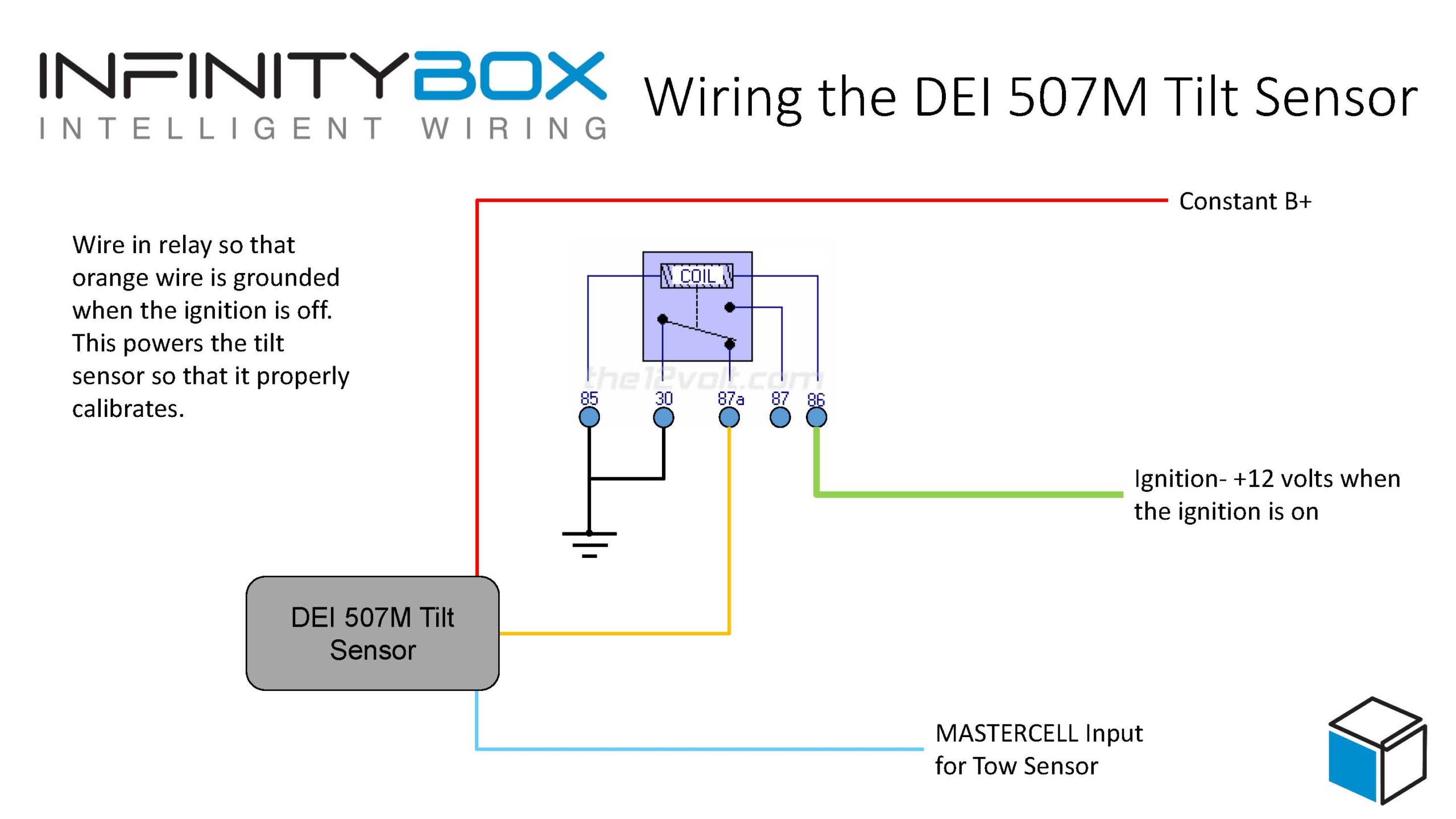
 Copyright Infinitybox, LLC 2021. All Rights Reserved.

 Copyright Infinitybox, LLC 2021. All Rights Reserved.

 Copyright Infinitybox, LLC 2021. All Rights Reserved.
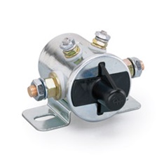

 Copyright Infinitybox, LLC 2021. All Rights Reserved.
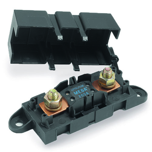
 Copyright Infinitybox, LLC 2021. All Rights Reserved.
 Copyright Infinitybox, LLC 2021. All Rights Reserved.
  Copyright Infinitybox, LLC 2021. All Rights Reserved.