We always say that our Infinitybox system plays nicely with other electrical accessories in your car. This blog post is another great example of that. We got a call from a customer asking about wiring the VaporWorx Fuel Pump Controller with his Infinitybox 20-Circuit Kit. He was worried about having to wire in additional relays and run a lot of wire. In reality, wiring the VaporWorx Fuel Pump Controller is simple and easy with the Infinitybox system.
The VaporWorx guys make some very cool products. Click here to get to their website. You have to appreciate a company with the tagline “We Give You Gas”. Their core products improve the delivery of fuel in your resto-mod, street rod, hot-rod or Pro-Touring build. They have been innovating products for reliable fuel delivery in cars with EFI systems since 2009.
Their core products are designed for returnless fuel systems. There is only one fuel line going from the in-tank pump to your fuel rail. There is no fuel regulator on the rail and no return line that brings excess fuel back to the tank. Their Fuel Pump Controller mounts in the rear of the car, near the fuel pump. It actively monitors the fuel pressure in the line at the outlet of the pump. Using pulse-width modulation (PWM), they vary the pump power to keep the fuel pressure within a tight window. This reduces dead-heading of the fuel pump and also reduces the amount that the fuel gets heated. We use PWM to control things like fan speed and light dimming from our POWERCELLs and have blogged about how that works before. Click on this link to learn more about PWM.
This blog post is going to walk you through wiring the VaporWorx fuel pump controller with our Infinitybox system. We are only going to cover the connections from the battery, from the POWERCELL and to ground. See their manual for more details on the rest of the sensor wiring required for their controller. You can access the manuals and installation instructions for their products by clicking this link.
Just like any other blog post where we talk about integrating the Infinitybox system with other products, please carefully read and understand all of the steps required to install the VaporWorx Fuel Pump Controller. You are messing with flammable fuel and electricity. Make sure you are completely comfortable with doing this job.
For the sake of this blog post, there are three connections that we are going to cover: primary power from the battery, the fuel pump trigger from the POWERCELL and the grounds.
The primary power for the fuel pump controller is going to come directly from the battery. This should be a simple connection since the controller should be mounted close to the pump in the tank and most guys are relocating their batteries to their trunks. Follow the recommendations from VaporWorx for the gauge of wire going from the positive terminal on the battery to the BAT+ terminal on their module. It is very important that this gauge of wire is sized correctly and that it is fused as close to the battery as possible.
Next, the fuel pump controller and the fuel pump need to be grounded. The VaporWorx team recommends that you ground their pump controller and the fuel pump directly to the negative terminal of the battery. This should be easy in most installs since guys are relocating the batteries to their trunks.
Last, the VaporWorx controller needs a fuel pump enable signal from the ECU. When wired with the Infinitybox system, this signal is going to come from the fuel pump output on your rear POWERCELL. In most 20-Circuit Kits, this is the TAN wire on the rear POWERCELL but check your configuration sheet for details on this output. The POWERCELL output is going to connect to the blue wire in the GT150 connector.
The advantage of using the POWERCELL to supply the fuel pump enable signal is that you do not need to add any additional wiring. You already have the POWERCELL located in the rear of your car. You do not need to run a wire from the front of the car to the back. You can simply use the POWERCELL to supply this signal.
Once you have power, ground and the fuel pump enable signal wired, you need to wire your EFI system to your Infinitybox MASTERCELL. This is how the POWERCELL knows when to turn on the output for the fuel pump enable signal. To do this properly, you need to understand if your EFI system uses a ground trigger for the fuel pump or a positive signal for the fuel pump. The wiring diagram for your EFI system will define this. Alternately, we have wiring diagrams for all of the popular EFI systems in the Resources section of our website.
If your EFI system sends a ground trigger for the fuel pump enable signal, you can wire the MASTERCELL fuel pump input to the EFI system’s fuel pump output. We strongly recommend wiring a diode in series to buffer the MASTERCELL from the ECU. As an example, the FAST XFI 2.0 sends a ground trigger for the fuel pump enable signal. You can see how the recommended diode is wired at this link.
If your EFI system sends a positive trigger for the fuel pump enable signal, you need to flip this to a ground trigger. You can use one of our inVERT Mini Buffers to do this easily. The Holley Sniper EFI System uses a positive trigger for the fuel pump enable signal. You can see how to wire in the inVERT Mini at this link.
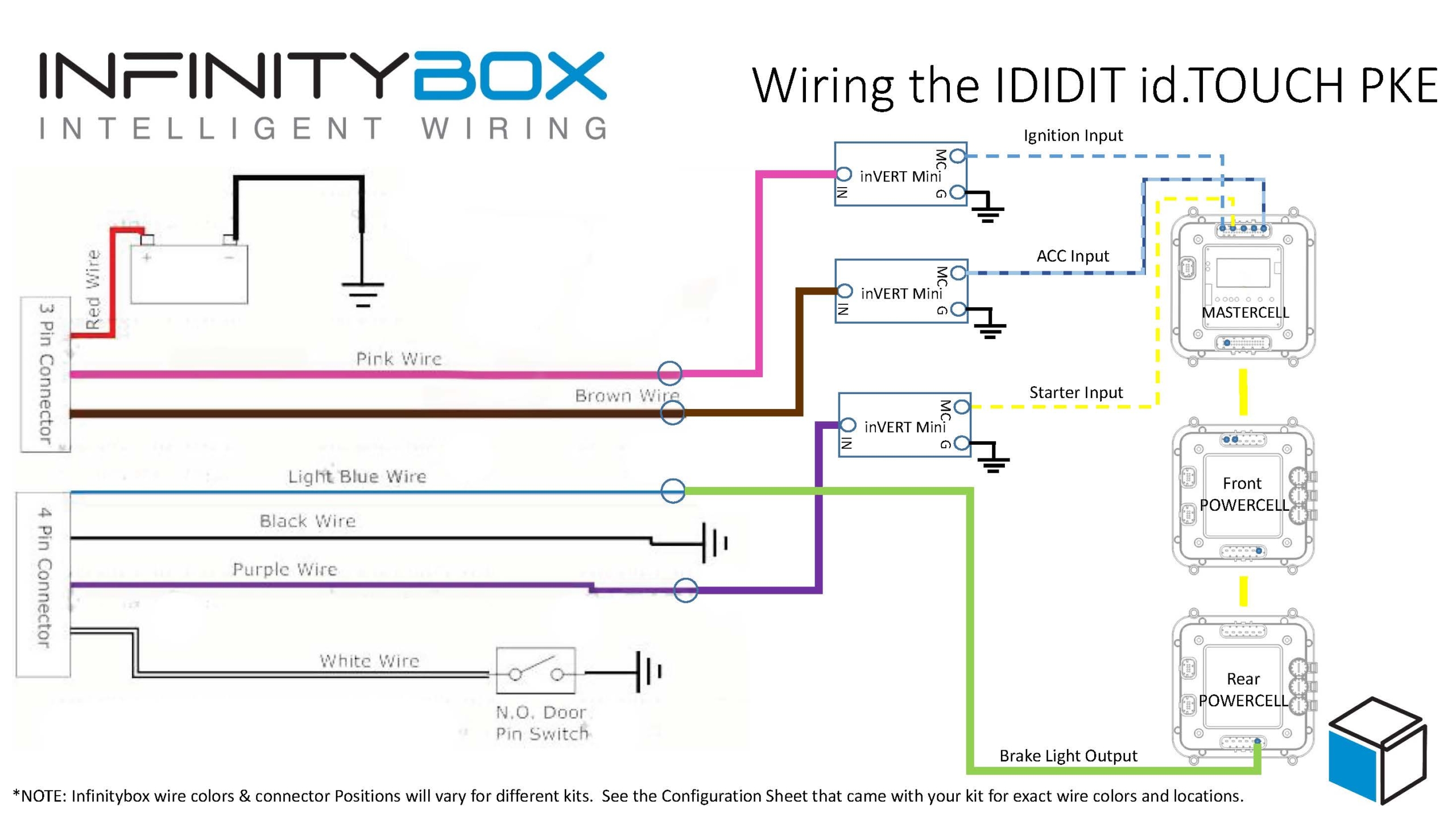
This wiring diagram shows you all of the connections between our Infinitybox system and the VaporWorx Fuel Pump Controller. You can download a PDF version of it by clicking this link.

Picture of the Infinitybox wiring diagram showing how to wire the VaporWorx Fuel Pump PWM controller with the Infinitybox system
Please note that some wires are omitted from our diagrams to make them more clear. Carefully follow the instructions that came with your Infinitybox system and the VaporWorx module for the full instructions. Also note that the MASTERCELL input and POWERCELL output wire colors may vary depending on your specific kit and the options you have. Always follow the configuration sheet that came with your kit.
Click on this link to contact our technical support team with any questions about wiring your VaporWorx Fuel Pump Controller with our Infinitybox system.
 Copyright Infinitybox, LLC 2021. All Rights Reserved.
  Copyright Infinitybox, LLC 2021. All Rights Reserved.


 Copyright Infinitybox, LLC 2021. All Rights Reserved.


 Copyright Infinitybox, LLC 2021. All Rights Reserved.

 Copyright Infinitybox, LLC 2021. All Rights Reserved.
  Copyright Infinitybox, LLC 2021. All Rights Reserved.