Posts

MASTERCELL NGX System Inventory

The System Inventory screen on your MASTERCELL NGX gives you a list of every device connected on your Infinitybox network. It is a simple but powerful tool that confirms your POWERCELLs, inMOTION Cells and other peripherals are connected, communicating and addressed correctly. This blog post is part of our series on the diagnostic functions built into the inSIGHT screen. We introduced this screen in our overview of the MASTERCELL NGX main menu. In this post, we take a deeper look at how to read and use the System Inventory screen.

Please note that this blog post covers the MASTERCELL NGX in our Next Generation IPM1 Kit. These inSIGHT diagnostic tools are specific to our Next Generation hardware. If you have our Legacy 3-Cell Kit or 20-Circuit Kit, search through our blog archives for the diagnostic tools that came with those systems.

How to Read the System Inventory Screen

To get to the System Inventory screen, press the HOME button on your MASTERCELL NGX to bring up the main menu, use the SCROLL UP and SCROLL DOWN buttons to move the cursor to System Inv and press SELECT.
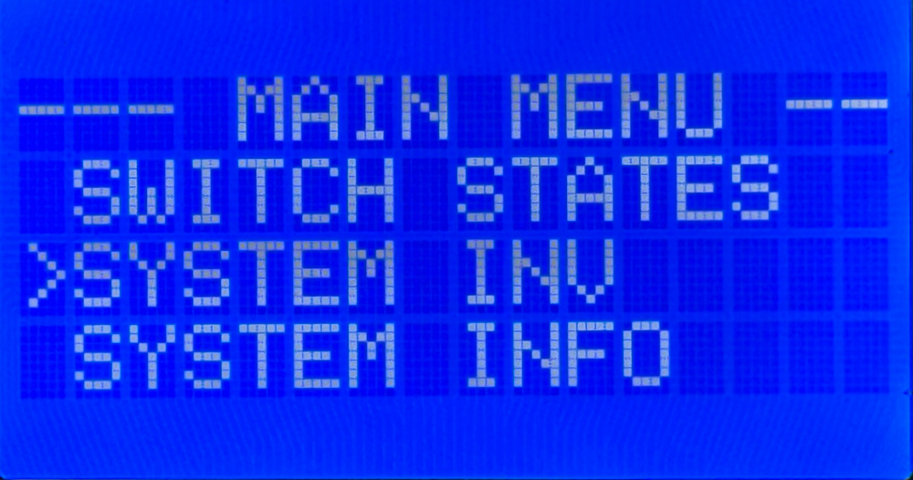
MASTERCELL NGX inSIGHT main menu with the cursor on the System Inv option.

Selecting System Inv from the MASTERCELL NGX main menu.

When the screen opens, you will see a list of every device that the MASTERCELL NGX finds on your network. The header at the top of the screen reads SYSTEM INV followed by a number in parentheses. That number tells you how many devices are on the network. It will change with the number of devices that are connected. In the example below, the header reads SYSTEM INV (3), so there are three devices on the network.
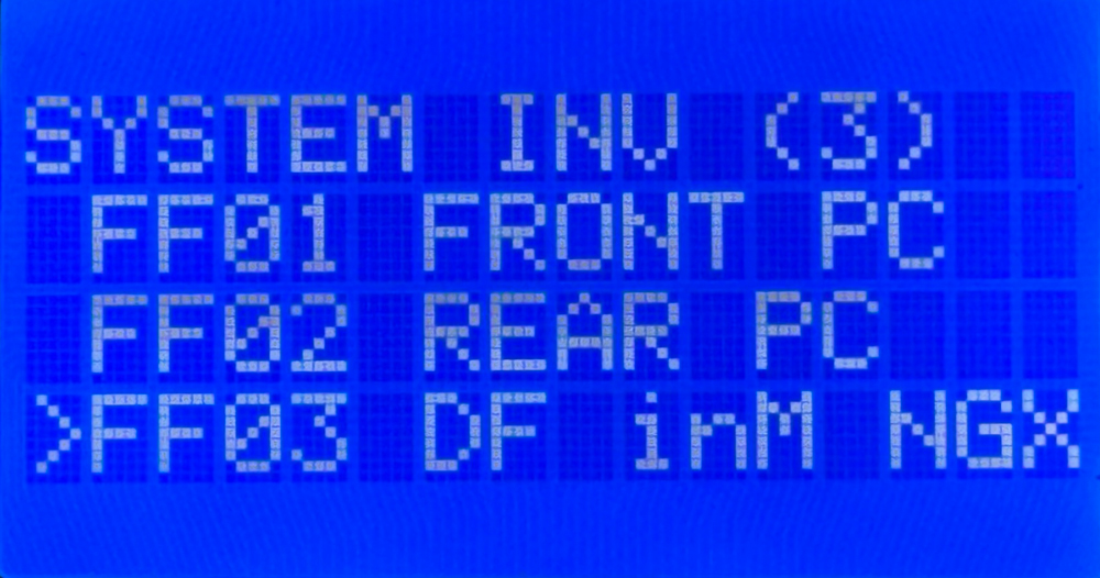
System Inventory screen on the MASTERCELL NGX inSIGHT display showing three connected devices with their PGN and name.

The System Inventory screen showing three devices on the network: a front POWERCELL, a rear POWERCELL, and a Driver Front inMOTION NGX.

Each device shows up on its own row with two pieces of information. On the left is the PGN for that device. This is an internal identifier that the MASTERCELL NGX uses to validate the device on the network. You do not need to decode it. On the right is the human-readable name that tells you what the device is. This is the part you will use to confirm what is connected.

You can use the SCROLL UP and SCROLL DOWN buttons to move the cursor through the list of devices. In a later blog post, we will show you how to use the SELECT button to drill down into a specific device and see much more detail about it, like the state of its outputs and its voltage. For this post, we are focused on the inventory list itself.

What the Devices Look Like on the Network

Each type of device in the Infinitybox system shows up in inventory with its own name so you can identify it at a glance. Here is what the different devices look like on the network.

  • POWERCELLs:
    • Address 1 shows as the front POWERCELL (FRONT PC)
    • Address 2 shows as the rear POWERCELL (REAR PC)
    • Additional POWERCELLs begin at FF07 and are labeled by number, such as POWERCELL 3
  • inMOTION Cells (FF03 through FF06):
    • Driver Front- DF inM NGX
    • Passenger Front- PF inM NGX
    • Driver Rear- DR inM NGX
    • Passenger Rear- PR inM NGX
  • inVIEW: inVIEW
  • inCONTROL: inCONTROL

Confirm Your Devices Are Connected and Communicating

The first thing the System Inventory screen tells you is whether every device you installed is actually on the network. When a device is powered correctly and its CAN cables are connected correctly, it announces itself to the MASTERCELL NGX and shows up in inventory.

Start with the device count in the header. Compare the number in parentheses to the number of devices you installed in your car. If you installed three POWERCELLs but the header only shows two, then one of them is not communicating. The same is true for any device in your system.

When a device is missing from inventory, it usually points to one of two things. Either the device is not being powered correctly, or there is a problem with the CAN cable that connects it to the rest of the network. The System Inventory screen lets you confirm quickly that every device is present before you spend time chasing a problem somewhere else.

Confirm Your Devices Are Addressed Correctly

The second thing the System Inventory screen tells you is whether each device is addressed as the device you intended. This is a more subtle problem, and it is one that can be very hard to find any other way.

Every POWERCELL is set to a specific address with its address jumpers. The MASTERCELL NGX sends commands to each POWERCELL based on that address. If a POWERCELL is addressed incorrectly, the commands meant for it never reach it, even though everything is powered and communicating perfectly.

Here is a common example. A customer is having trouble getting the outputs on a POWERCELL to work. Everything is wired correctly and the cell is communicating, but the functions still do not work. After some troubleshooting, we find that the address jumpers were set to the wrong cell. Instead of being set to cell 1, the POWERCELL was set to cell 8. The System Inventory screen makes this easy to spot. The customer can look at inventory and see that a device is on the network, but it is not showing up as the cell they intended it to be. That tells them the address is wrong.

This is what makes the System Inventory screen so powerful. It takes an invisible problem, a device that is powered and communicating but addressed incorrectly, and makes it visible. We will cover how to set and change device addresses in more detail in a later blog post.

Summary

The System Inventory screen on the MASTERCELL NGX inSIGHT display gives you a quick, at-a-glance list of every device on your Infinitybox network. Use it to confirm that every device you installed is powered and communicating, and to confirm that each device is addressed as the cell you intended. Paired with the other diagnostic tools on the inSIGHT screen, it is one of the fastest ways to understand what is happening on your network.

Keep watching our blog for more details on the menus and diagnostic functions on the inSIGHT screen. If you have any questions, give us a call at (847) 232-1991 or contact us here.
MASTERCELL NGX Main Menu

The inSIGHT LCD screen on your MASTERCELL NGX is your window into your Infinitybox system. From the main menu, you can set up key features and access a powerful set of diagnostic tools with a few simple button presses. We covered the main status screen that you see when your system powers up in a separate blog post. You can learn about the main screen and how to read your CAN, ignition and security status by clicking this link. In this post, we want to walk through the six options on the MASTERCELL NGX main menu and explain what each one does. We will follow up with separate blog posts that take a deeper dive into each option.

Please note that this blog post covers the MASTERCELL NGX in our Next Generation IPM1 Kit. These inSIGHT diagnostic tools are specific to our Next Generation hardware. If you have our Legacy 3-Cell Kit or 20-Circuit Kit, search through our blog archives for the inSIGHT diagnostic tools that came with those systems.

The MASTERCELL NGX Main Menu

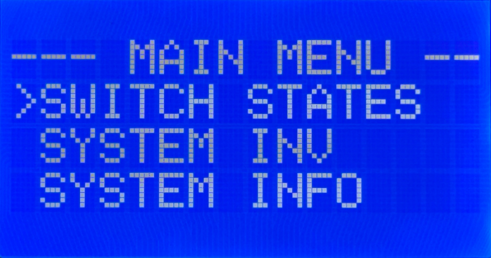
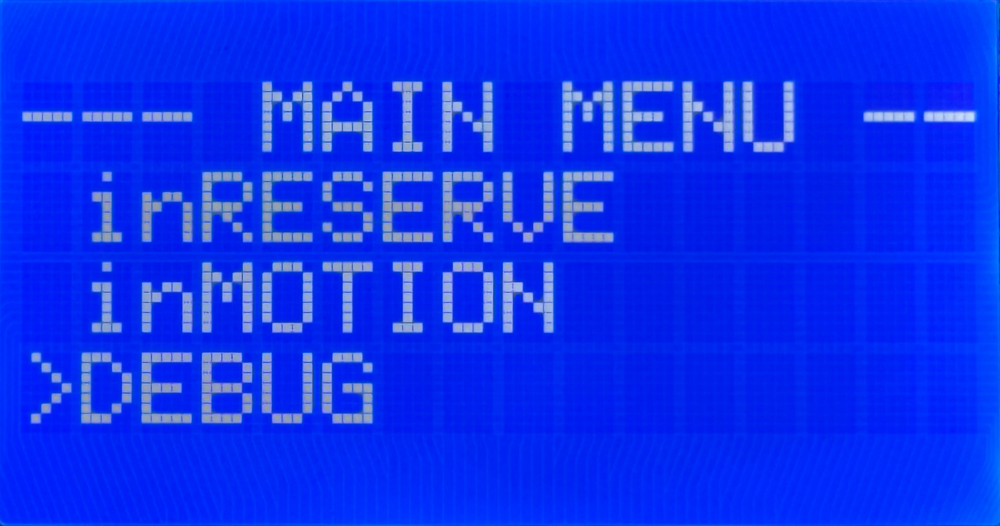
To get to the main menu, press and release the HOME button on your MASTERCELL NGX. The main menu has six options. You use the SCROLL UP and SCROLL DOWN buttons to move the cursor through the list and the SELECT button to open the option that the cursor is pointing to. Because the menu is longer than the screen, you will scroll through two views to see all six options.

MASTERCELL NGX inSIGHT main menu showing the Switch States, System Inv, and System Info options.

The top of the MASTERCELL NGX main menu, with options for Switch States, System Inv, and System Info.

MASTERCELL NGX inSIGHT main menu scrolled to show the inRESERVE, inMOTION, and DEBUG options.

The MASTERCELL NGX main menu scrolled down to the inRESERVE, inMOTION, and DEBUG options.

The six options are Switch States, System Inv, System Info, inRESERVE, inMOTION and DEBUG. Let’s walk through each one.

Switch States

The Switch States option gives you a real-time view of every switch input on your MASTERCELL NGX. The MASTERCELL NGX has 38 ground-switched inputs and 6 high-side switched inputs. When you open Switch States, you see a screen of digits arranged across four rows. The ground-switched inputs run across the rows, and the six high-side input states appear on the right side of the bottom row. A 0 means the input is off and a 1 means the input is on. The screen updates in real time, so if a switch turns on or off while you are watching, you will see it change, with a lag of up to one second.

This is a powerful way to confirm that your switches are wired correctly. You can work through your car one switch at a time and watch the screen confirm that the MASTERCELL NGX sees each input.  Click on this link to take the deeper dive into the Switch States feature on the MASTERCELL NGX.

System Inventory

The System Inv option is your system inventory screen. It gives you a list of every peripheral connected to your MASTERCELL NGX. This can include POWERCELLs, inMOTION Cells, inVIEW Cells and inCONTROL knobs. Each device shows up with its CAN address and a name so you can confirm that the MASTERCELL NGX sees everything in your network.

You can use the SCROLL UP and SCROLL DOWN buttons to highlight a device in the inventory and the SELECT button to dig deeper into it. From there, you can see details like the state of its outputs, its voltage and more. Click here for more details on the System Inventory function.

System Info

The System Info option lets you see the software revision of the code loaded onto your system. It also shows you the configuration that is loaded. The IPM1 Kit has options for a front-engine configuration and a rear-engine configuration, along with the option for a Custom configuration. If your system shows a Custom configuration and you have questions about it, contact our technical support team for more information. You can learn more about how to read the software revision and the loaded configuration by clicking this link.  

inRESERVE

The inRESERVE option lets you set up our inRESERVE Active Battery Management accessory. inRESERVE connects a POWERCELL output to a special latching solenoid and monitors your battery voltage. When the ignition is off and the voltage drops below a set threshold for a period of time, the POWERCELL pulses the solenoid and disconnects power to the system. This proactively eliminates drain from your battery.

Every IPM1 Kit ships without inRESERVE set up. If you purchase the inRESERVE option, this menu lets you enable the feature, pick the POWERCELL and output that control the solenoid, and choose the timing and voltage threshold. We have an existing blog post that walks through this whole process. You can learn how to enable inRESERVE on your MASTERCELL NGX by clicking this link.

inMOTION

The inMOTION option walks you through the process of setting up your inMOTION NGX door modules. inMOTION NGX installs in the door, and each module must be set with its proper address so it knows which commands to obey. The default locations are Driver Front, Passenger Front, Driver Rear and Passenger Rear. You order as many inMOTION NGX modules as you need for your build, two for a 2-door car or four for a 4-door car. We ship them set up generically, so you run this process once to tell each module where it is installed in the car. You can learn how to configure your inMOTION NGX door modules by clicking this link.

DEBUG

The DEBUG option puts the MASTERCELL NGX into what we call Messaging Mode. Where Switch States shows you whether an input is on or off, Messaging Mode goes a step deeper. It displays in real time when the MASTERCELL NGX sees an input turn on or off, and then shows you what the MASTERCELL NGX does in response.

This is a powerful tool for confirming that your switches are wired correctly and that your MASTERCELL NGX is programmed the way you expect. For example, if your headlights are not working, you can put the MASTERCELL NGX into Messaging Mode and turn the headlight switch on. The inSIGHT screen will display the input it saw turn on and confirm which POWERCELL and which output it is commanding to turn on. We will take a closer look at Messaging Mode in its own blog post.

Summary

The main menu on the MASTERCELL NGX inSIGHT display is your gateway to the setup and diagnostic functions built into your Next Generation Infinitybox system. From these six options, you can check your switches, review your system inventory, see your software and configuration, set up inRESERVE, configure your inMOTION NGX modules and dig into advanced diagnostics with Messaging Mode. Keep watching our blog as we publish a detailed deep dive into each one.

Give us a call at (847) 232-1991 or contact us here if you have any questions.

Picture of Lokar 12-Volt Door Handle

Door Poppers with the Lokar 12-Volt Door Switches

How to Wire Lokar 12-Volt Door Handles to Infinitybox Systems for Door Poppers

Wondering how to connect Lokar 12-volt door handles to your Infinitybox system? This comprehensive guide shows you how to wire Lokar billet door handles with door popper solenoids using both the Legacy 20-Circuit Kit and the new inMOTION NGX system.

Understanding Lokar 12-Volt Billet Door Handles

Lokar manufactures premium billet accessories for custom cars and trucks. Their Billet Exterior 12-Volt Door Handles combine classic styling with modern functionality, featuring an integrated switch that activates door popper solenoids when you pull the handle. These bolt-on handles provide a sleek, modern touch to any vehicle’s exterior doors.

Learn more about Lokar Billet Exterior 12-Volt Door Handles

Wiring Lokar Door Handles with the Legacy 20-Circuit Infinitybox System

The Legacy Infinitybox system makes it simple to integrate Lokar door handles with electric door poppers. Follow these step-by-step instructions:

Installation Steps

1. Install the Hardware

  • Mount the Lokar door handles according to manufacturer instructions
  • Install door popper solenoids in each door per the included guidelines

2. Connect POWERCELL Outputs

  • Select OPEN outputs on your POWERCELL module for each door
  • Connect the POWERCELL output wire to one lead on the door popper solenoid
  • Ground the other solenoid lead

3. Wire MASTERCELL Inputs

  • Connect the MASTERCELL input (corresponding to your OPEN output) to the switch inside the Lokar door handle
  • Ground the remaining switch wire

How It Works

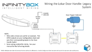
When you pull the Lokar door handle, the MASTERCELL input grounds out. This triggers the MASTERCELL to command the POWERCELL to activate the output, pulsing the door popper solenoid and releasing the door latch.

Picture of Wiring diagram showing how to wire the Lokar 12-volt Door Handle to the Legacy Infinitybox System to control door poppers.

Picture of Wiring diagram showing how to wire the Lokar 12-volt Door Handle to the Legacy Infinitybox System to control door poppers.

Bonus Security Feature: We can program your system to block door popper switches when security is enabled via inLINK or inTOUCH NET. This ensures doors only open when you disable security using your inLINK key fob or smartphone app.

Wiring Lokar Door Handles with inMOTION NGX System

The Next Generation inMOTION NGX simplifies the installation even further. This door-mounted control module features two H-Bridge relays designed for power locks and power windows.

Simplified NGX Installation

The inMOTION NGX installs directly inside your door, keeping all wiring localized:

  • Use one output from the power lock relay pair to control the door popper solenoid
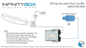
  • Wire the Lokar door handle switch directly to the inMOTION NGX in the same door
  • Control both the switch input and popper output from a single module

This configuration dramatically reduces wiring complexity compared to traditional systems.

Picture of wiring diagram showing how to wire the Locar 12-Volt Door Handles to control door poppers using the Infinitybox inMOTION NGX door control module.

Picture of wiring diagram showing how to wire the Locar 12-Volt Door Handles to control door poppers using the Infinitybox inMOTION NGX door control module.

The inMOTION NGX also supports security integration, allowing you to configure door poppers to function only when the vehicle security system is disarmed.

Download Wiring Diagrams

Need Help with Your Infinitybox Installation?

Our team is ready to answer your questions about connecting Lokar door handles or any other Infinitybox wiring project. Contact us at (847) 232-1991 or click here to reach our support team.


Keywords: Lokar 12-volt door handles, Infinitybox wiring, door popper solenoid, inMOTION NGX, Legacy 20-Circuit Kit, billet door handles, electric door poppers, POWERCELL, MASTERCELL, custom car wiring