Posts

Messaging Mode on the MASTERCELL NGX

The DEBUG option on your MASTERCELL NGX puts the module into what we call Messaging Mode. It is the deepest diagnostic tool built into the inSIGHT screen. Where the Switch States screen shows you whether an input is on or off, Messaging Mode goes a step further. It shows you what the MASTERCELL NGX does in response to that input, in real time, right on the screen. This blog post is part of our series on the diagnostic functions built into the inSIGHT screen. We introduced this option in our overview of the MASTERCELL NGX main menu, and it works hand in hand with the Switch States screen. In this post, we take a closer look at how to read and use Messaging Mode.

Please note that this blog post covers the MASTERCELL NGX in our Next Generation IPM1 Kit. These inSIGHT diagnostic tools are specific to our Next Generation hardware. If you have our Legacy 3-Cell Kit or 20-Circuit Kit, search through our blog archives for the diagnostic tools that came with those systems.

How Cases Work

To understand what Messaging Mode is showing you, it helps to understand cases. Every input on your MASTERCELL NGX has cases assigned to it. These cases tell the MASTERCELL NGX what messages to send out across the Infinitybox network when that input changes state.

Cases are split into two groups. There are cases for when a switch turns on and cases for when a switch turns off. The number of cases varies from one input to the next. Some inputs have a single ON case and no OFF cases. Others have a single ON case and a single OFF case. Others have multiple ON cases and multiple OFF cases. This is what lets a single switch control multiple outputs across your network at the same time. A simple input like your horn has one ON case that controls one output. A more involved input like your ignition can carry several ON cases and several OFF cases, so turning the key can power your EFI system, bring up accessories in the back of the car and more, all at once.

You can view and modify the cases assigned to each input using our inCODE NGX programming tool. We will cover how to create and change cases in a future blog post and video series dedicated to inCODE NGX. For this post, all you need to know is that cases exist, that they are split into ON and OFF cases, and that the number of cases depends on the input. That is what Messaging Mode puts on the screen.

Entering Messaging Mode

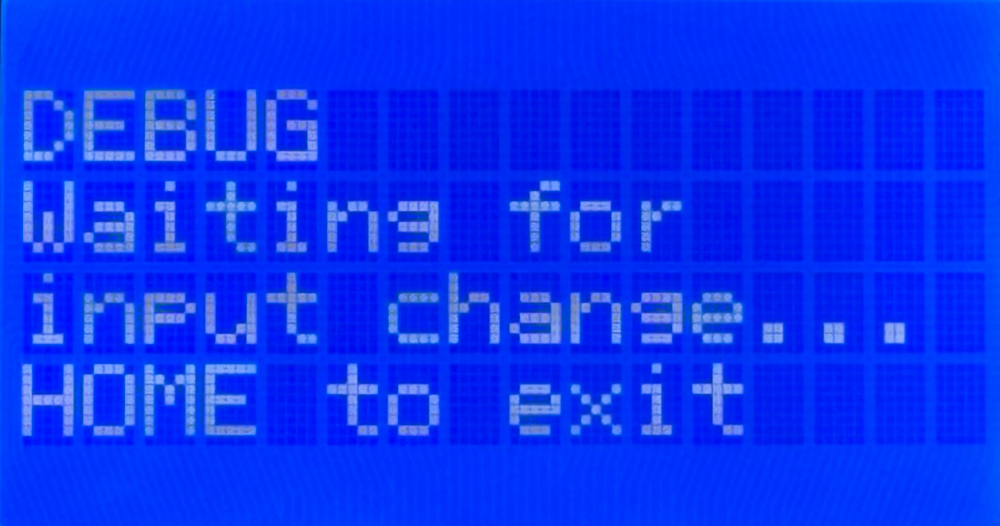
To enter Messaging Mode, press the HOME button on your MASTERCELL NGX to bring up the main menu, scroll to DEBUG and press SELECT. You will see a screen telling you the MASTERCELL NGX is waiting for an input to change.

MASTERCELL NGX inSIGHT screen in Messaging Mode showing DEBUG and Waiting for input change

The MASTERCELL NGX in Messaging Mode, waiting for an input to change. Press HOME to exit.

The MASTERCELL NGX stays in Messaging Mode until you press the HOME button, which takes you back to the main menu. While the MASTERCELL NGX is in Messaging Mode, the backlight stays on. This is different from normal operation, where the screen and the backlight both turn off to minimize battery draw. If the backlight is on, you know the MASTERCELL NGX is still in Messaging Mode.

Watching a Single-Case Input

Let’s start with a simple input. On a standard system, your horn is input 9. Always check the configuration sheet that came with your kit to confirm the input and output numbers for your build, because your configuration sheet is the single point of truth for input numbers, output numbers and wire colors.

With the MASTERCELL NGX in Messaging Mode, press the horn button. The screen shows you what the MASTERCELL NGX saw and what it did in response.

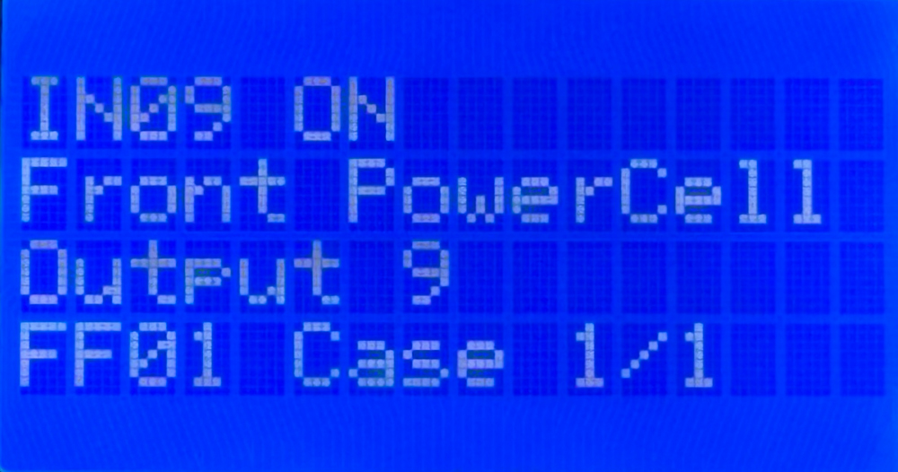
MASTERCELL NGX inSIGHT screen in Messaging Mode showing input 9 on commanding output 9 on the Front POWERCELL

Turning the horn on. Messaging Mode shows input 9 commanding output 9 on the Front POWERCELL.

Reading this screen from the top: the first line, IN09 ON, tells you the MASTERCELL NGX saw input 9 turn on. The second line, Front PowerCell, tells you which cell it is commanding. The third line, Output 9, tells you which output on that cell. The fourth line, FF01 Case 1/1, tells you two things. FF01 is the internal address we use for the Front POWERCELL. Case 1/1 tells you this is case 1 of 1, meaning this input has a single case assigned to its ON state.

Now release the horn button. The screen updates to confirm the input turned off.

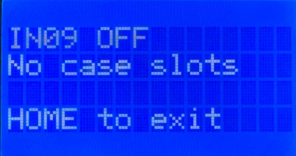
MASTERCELL NGX inSIGHT screen in Messaging Mode showing input 9 off with no case slots

Releasing the horn. Messaging Mode confirms input 9 turned off. The horn input has no OFF case slots.

The first line, IN09 OFF, confirms the MASTERCELL NGX saw input 9 turn off. This is useful on its own, because it confirms the switch released cleanly and is not hung on. The second line reads No case slots. This tells you the horn input has no case slots available for its OFF state. There is nothing for the MASTERCELL NGX to command when the horn turns off, which is exactly how the horn is designed to work.

Watching a Multi-Case Input

Now let’s look at a more involved input. On a standard system, your ignition is input 1. Again, confirm this against your own configuration sheet.

With the MASTERCELL NGX in Messaging Mode, turn the ignition on. The screen shows the first case.

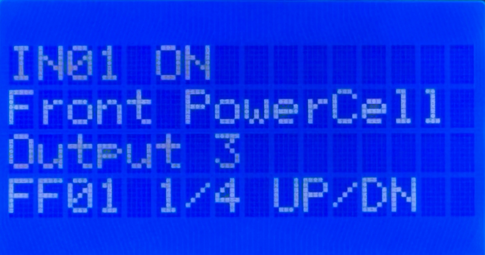
MASTERCELL NGX inSIGHT screen in Messaging Mode showing input 1 on commanding output 3 on the Front POWERCELL, case 1 of 4

Turning the ignition on. Messaging Mode shows the first of four ON cases, with UP and DN to scroll through the rest.

This screen reads much like the horn did. Input 1 turned on, and the MASTERCELL NGX is commanding output 3 on the Front POWERCELL. The difference is on the fourth line. FF01 1/4 tells you this is case 1 of 4, so this input has four cases assigned to its ON state. The UP/DN prompt tells you to use the SCROLL UP and SCROLL DOWN buttons to step through the rest of the cases. This prompt takes the place of the HOME to exit line, but the HOME button still exits Messaging Mode.

Scroll down to see the next case.

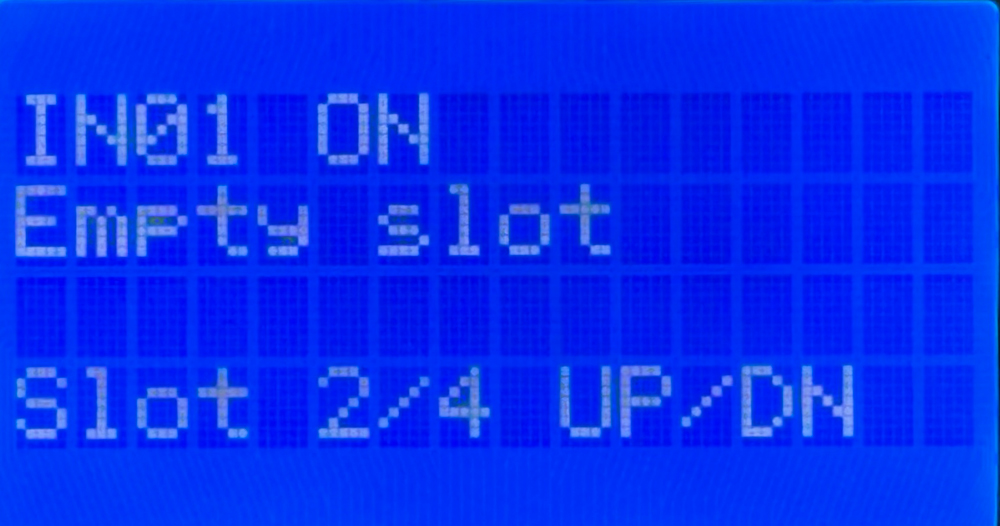
MASTERCELL NGX inSIGHT screen in Messaging Mode showing input 1 on with an empty case slot, slot 2 of 4

The second slot for the ignition input is empty. Available slots that are not programmed show Empty slot.

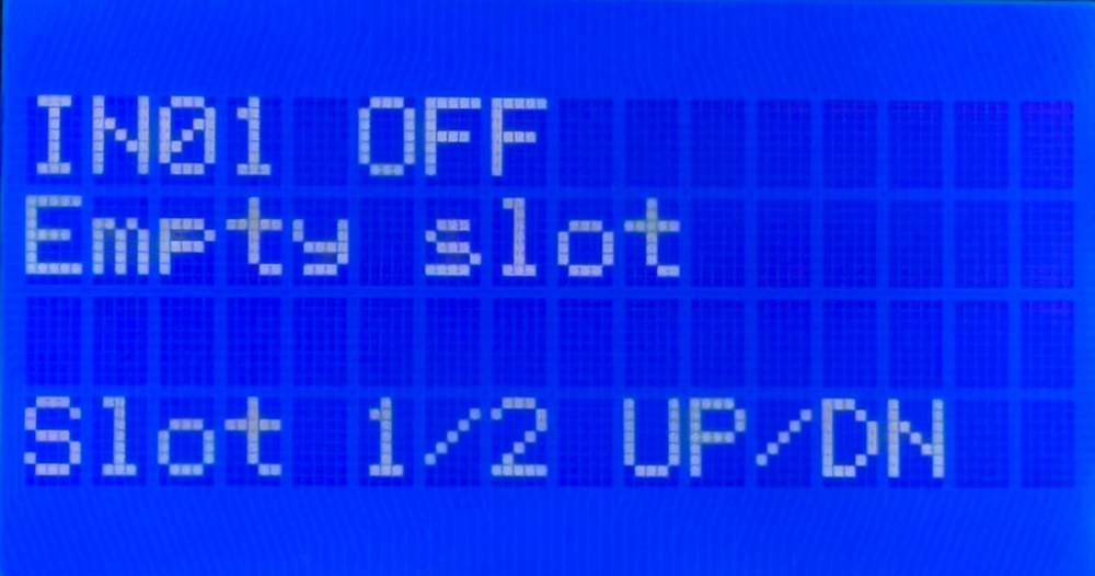
This screen shows an empty slot. The default ignition configuration uses only the first ON case, but there are four slots available. The second line reads Empty slot, meaning this slot is available but has nothing assigned to it. Notice the fourth line reads Slot 2/4 instead of leading with an address like FF01. That is because an empty slot has no cell or output assigned to it, so there is no internal address to display.

This is worth pausing on, because it is a different situation from the horn. When the horn turned off, the screen read No case slots, meaning no slots exist for that state at all. Here the screen reads Empty slot, meaning the slot exists and is available, it just has not been programmed. You would keep scrolling to view the remaining slots for this input.

When you turn the ignition off, Messaging Mode confirms the input turned off and shows you the cases assigned to its OFF state.

MASTERCELL NGX inSIGHT screen in Messaging Mode showing input 1 off with two available OFF cases

Turning the ignition off. Messaging Mode confirms input 1 turned off and shows two OFF cases to scroll through.

The first line confirms input 1 turned off. The fourth line shows this input has two cases available for its OFF state, with the UP/DN prompt to scroll through them. OFF cases are what let your system do something when a switch turns off, such as running a cooling fan for a set period of time after you shut off the ignition.

What This Tells You

Messaging Mode is one of the most powerful troubleshooting tools in your Infinitybox system because it confirms the whole chain from your switch to your output. Say your horn is not working. Put the MASTERCELL NGX into Messaging Mode and press the horn button. Watching the screen tells you three things at once.

First, it confirms your switch is working. If IN09 ON appears when you press the button, the switch is doing its job and the MASTERCELL NGX is seeing it. If nothing appears, the problem is upstream at the switch or its wiring, not in the rest of the system.

Second, it confirms you have the correct MASTERCELL NGX input wire connected to your switch. If you press the horn button and the screen shows a different input number, you know the wrong input wire is landed on that switch, and you can correct it.

Third, it confirms the correct cell and output are being commanded. The screen shows you exactly which POWERCELL and which output the MASTERCELL NGX is telling to turn on, so you can confirm the command is going where you expect and check your configuration sheet against what you see.

Working through your car this way takes the guesswork out of troubleshooting. Instead of chasing a problem blind, you can watch the MASTERCELL NGX see your switch and command your output, and pinpoint exactly where the chain breaks down.

You can download the entire MASTERCELL NGX inSIGHT document by clicking this link.  This includes all the features and functions.

Questions?

Messaging Mode gives you a real-time window into how your MASTERCELL NGX responds to every switch in your car. It is one more diagnostic tool built into the inSIGHT screen to help you wire and troubleshoot with confidence. If you have any questions about Messaging Mode or any other part of your Infinitybox system, contact our technical support team through our contact form or give us a call at (847) 232-1991.

Polling Your Cells with the MASTERCELL NGX

The System Inventory screen on your MASTERCELL NGX shows you a list of every device connected on your Infinitybox network. Once you know a device is there, you can dig deeper into it to see how it is working. We call this polling. When you poll a cell, the MASTERCELL NGX shows you real-time information about that device right on the inSIGHT screen. This blog post is part of our series on the diagnostic functions built into the inSIGHT screen. We introduced the inventory list in our post on the MASTERCELL NGX System Inventory screen. In this post, we take the next step and poll the cells in that inventory.

The MASTERCELL NGX brings this powerful diagnostic capability to the Next Generation IPM1 Kit and puts it on the inSIGHT screen where it is easy to reach.  There is much more information given on our Next Generation System than on our Legacy System.

Please note that this blog post covers the MASTERCELL NGX in our Next Generation IPM1 Kit. These inSIGHT diagnostic tools are specific to our Next Generation hardware. If you have our Legacy 3-Cell Kit or 20-Circuit Kit, search through our blog archives for the diagnostic tools that came with those systems.

How to Poll a Cell

Start at the System Inventory screen. Press the HOME button on your MASTERCELL NGX to bring up the main menu, use the SCROLL UP and SCROLL DOWN buttons to move the cursor to System Inv and press SELECT. This brings up the list of every device on your network.

Use the SCROLL UP and SCROLL DOWN buttons to move the cursor to the device you want to poll, then press SELECT. The MASTERCELL NGX drills into that device and shows you its details. What you see next depends on the type of device you selected. We will walk through each one below.

Polling a POWERCELL

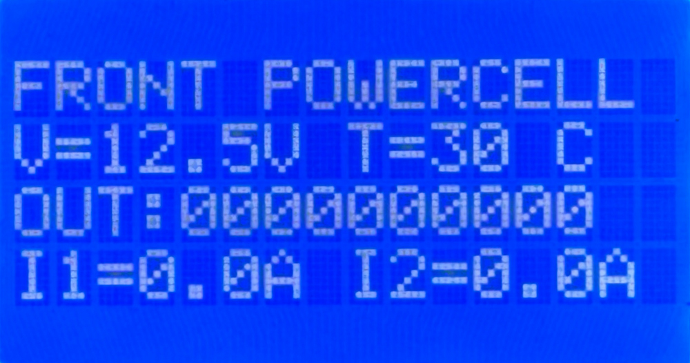
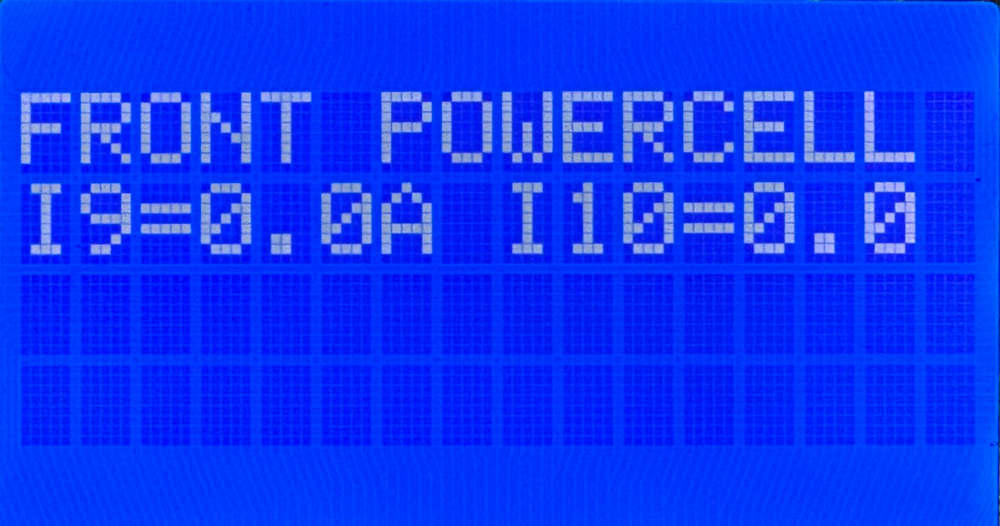
When you poll a POWERCELL, the first line of the screen tells you which POWERCELL you are looking at, such as FRONT POWERCELL or REAR POWERCELL. This confirms you are polling the cell you intended to.

The next line shows two values. The first is the battery voltage measured locally at the POWERCELL, shown as V=12.5V. This is the voltage right at the cell, which is useful for confirming the POWERCELL is getting good power. The second value is the temperature of the POWERCELL in degrees Celsius, shown as T=30 C.

MASTERCELL NGX inSIGHT screen polling the Front POWERCELL showing voltage, temperature, output states and current for outputs 1 and 2

Polling the Front POWERCELL. The first screen shows battery voltage, cell temperature, the state of all 10 outputs and the current for outputs 1 and 2.

The next line shows the state of all 10 outputs on the POWERCELL. There are 10 digits on this line. Reading from left to right, they correspond to outputs 1 through 10. If a digit is a zero, that output is off. If it is a one, that output is on. This lets you see at a glance which outputs the POWERCELL is commanding on and which are off.

Below the output states, the screen shows the current draw for each output. Each value is displayed as IX=Y.YA, where X is the output number and Y.Y is the current flowing through that output in amps. These current values update in real time. The first POWERCELL screen shows the current for outputs 1 and 2.

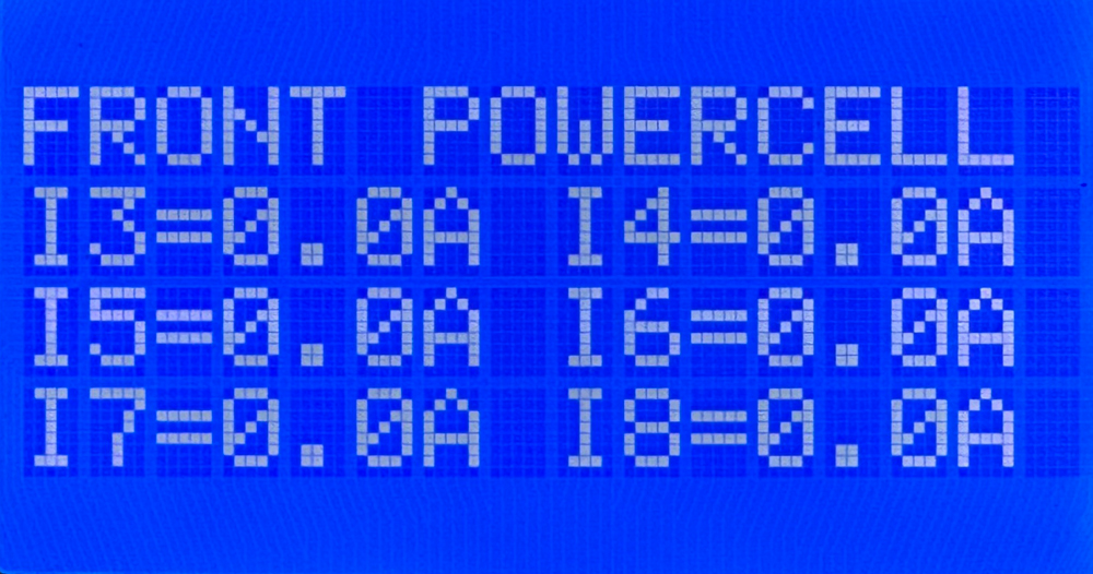
Because a POWERCELL has 10 outputs, the current values run across three screens. Use the SCROLL UP and SCROLL DOWN buttons to move through them. The first screen shows the current for outputs 1 and 2. The second screen shows outputs 3 through 8. The third screen shows outputs 9 and 10.

MASTERCELL NGX inSIGHT screen polling the Front POWERCELL showing real-time current for outputs 3 through 8

The second POWERCELL poll screen shows the real-time current draw for outputs 3 through 8.

MASTERCELL NGX inSIGHT screen polling the Front POWERCELL showing real-time current for outputs 9 and 10

The third POWERCELL poll screen shows the real-time current draw for outputs 9 and 10.

Using the POWERCELL Poll to Troubleshoot

The real power of polling a POWERCELL comes from reading the output states and the current draw together. The output state tells you what the POWERCELL is commanding. The current draw tells you what is actually happening on the wire. When those two disagree, you have found a problem.

Here is the case to watch for. You command an output on and its digit on the output line reads one, but the current for that output reads 0.0A. The POWERCELL is doing its job and switching the output on, but no current is flowing. That points you to a break somewhere in that circuit. The most common causes are a blown fuse, a broken wire, a bad ground or a burned-out bulb. Any one of these breaks the path that current needs to flow through, so the output turns on but nothing draws power.

The healthy case is just as useful. When you command an output on and the current reading matches the load you expect for that circuit, you have confirmed the whole circuit is good from the POWERCELL all the way through to the load and back to ground. Being able to see that real current in real time takes the guesswork out of troubleshooting and points you straight at the circuit that needs attention.

Polling an inMOTION Cell

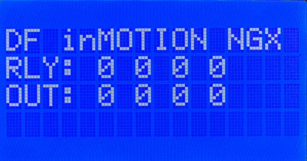
When you poll an inMOTION Cell, the first line of the screen tells you which inMOTION Cell you are looking at. The MASTERCELL NGX identifies it by its door position, such as DF for Driver Front, PF for Passenger Front, DR for Driver Rear or PR for Passenger Rear.

MASTERCELL NGX inSIGHT screen polling the Driver Front inMOTION Cell showing the state of the relay and MOSFET outputs

Polling the Driver Front inMOTION Cell. The RLY line shows the state of the four relay outputs and the OUT line shows the state of the four MOSFET outputs.

The inMOTION Cell has two rows of output states. The RLY line shows the state of the four relay outputs. These come from the two H-bridge relays inside the inMOTION Cell that drive functions like your power windows and power door locks. The OUT line shows the state of the four MOSFET outputs. As with the POWERCELL, a zero means that output is off and a one means it is on.

To see how the outputs on your inMOTION Cell are mapped to the functions in your car, check the configuration sheet that came with your IPM1 Kit. Your configuration sheet is the single point of truth for how each output is assigned in your system.

Polling inVIEW and inCONTROL

Your inVIEW and inCONTROL peripherals will appear in the System Inventory list along with your POWERCELLs and inMOTION Cells. This confirms that they are connected and communicating on your network. In the current version of our software, polling an inVIEW or an inCONTROL does not display any information. They show up in inventory, but there is no detail screen to drill into.

You can download the entire MASTERCELL NGX inSIGHT document by clicking this link.  This includes all the features and functions.

Questions?

Polling your cells from the MASTERCELL NGX gives you a clear, real-time view of what every device on your network is doing. It is one more diagnostic tool built into the inSIGHT screen to help you wire and troubleshoot your car with confidence. If you have any questions about polling your cells or any other part of your Infinitybox system, contact our technical support team through our contact form or give us a call at (847) 232-1991.

MASTERCELL NGX System Inventory

The System Inventory screen on your MASTERCELL NGX gives you a list of every device connected on your Infinitybox network. It is a simple but powerful tool that confirms your POWERCELLs, inMOTION Cells and other peripherals are connected, communicating and addressed correctly. This blog post is part of our series on the diagnostic functions built into the inSIGHT screen. We introduced this screen in our overview of the MASTERCELL NGX main menu. In this post, we take a deeper look at how to read and use the System Inventory screen.

Please note that this blog post covers the MASTERCELL NGX in our Next Generation IPM1 Kit. These inSIGHT diagnostic tools are specific to our Next Generation hardware. If you have our Legacy 3-Cell Kit or 20-Circuit Kit, search through our blog archives for the diagnostic tools that came with those systems.

How to Read the System Inventory Screen

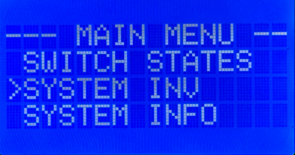
To get to the System Inventory screen, press the HOME button on your MASTERCELL NGX to bring up the main menu, use the SCROLL UP and SCROLL DOWN buttons to move the cursor to System Inv and press SELECT.

MASTERCELL NGX inSIGHT main menu with the cursor on the System Inv option.

Selecting System Inv from the MASTERCELL NGX main menu.

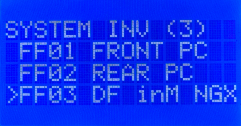
When the screen opens, you will see a list of every device that the MASTERCELL NGX finds on your network. The header at the top of the screen reads SYSTEM INV followed by a number in parentheses. That number tells you how many devices are on the network. It will change with the number of devices that are connected. In the example below, the header reads SYSTEM INV (3), so there are three devices on the network.

System Inventory screen on the MASTERCELL NGX inSIGHT display showing three connected devices with their PGN and name.

The System Inventory screen showing three devices on the network: a front POWERCELL, a rear POWERCELL, and a Driver Front inMOTION NGX.

Each device shows up on its own row with two pieces of information. On the left is the PGN for that device. This is an internal identifier that the MASTERCELL NGX uses to validate the device on the network. You do not need to decode it. On the right is the human-readable name that tells you what the device is. This is the part you will use to confirm what is connected.

You can use the SCROLL UP and SCROLL DOWN buttons to move the cursor through the list of devices. In this separate blog post, we show you how to use the SELECT button to drill down into a specific device and see much more detail about it, like the state of its outputs and its voltage. For this post, we are focused on the inventory list itself.

What the Devices Look Like on the Network

Each type of device in the Infinitybox system shows up in inventory with its own name so you can identify it at a glance. Here is what the different devices look like on the network.

  • POWERCELLs:
    • Address 1 shows as the front POWERCELL (FRONT PC)
    • Address 2 shows as the rear POWERCELL (REAR PC)
    • Additional POWERCELLs begin at FF07 and are labeled by number, such as POWERCELL 3
  • inMOTION Cells (FF03 through FF06):
    • Driver Front- DF inM NGX
    • Passenger Front- PF inM NGX
    • Driver Rear- DR inM NGX
    • Passenger Rear- PR inM NGX
  • inVIEW: inVIEW
  • inCONTROL: inCONTROL

Confirm Your Devices Are Connected and Communicating

The first thing the System Inventory screen tells you is whether every device you installed is actually on the network. When a device is powered correctly and its CAN cables are connected correctly, it announces itself to the MASTERCELL NGX and shows up in inventory.

Start with the device count in the header. Compare the number in parentheses to the number of devices you installed in your car. If you installed three POWERCELLs but the header only shows two, then one of them is not communicating. The same is true for any device in your system.

When a device is missing from inventory, it usually points to one of two things. Either the device is not being powered correctly, or there is a problem with the CAN cable that connects it to the rest of the network. The System Inventory screen lets you confirm quickly that every device is present before you spend time chasing a problem somewhere else.

Confirm Your Devices Are Addressed Correctly

The second thing the System Inventory screen tells you is whether each device is addressed as the device you intended. This is a more subtle problem, and it is one that can be very hard to find any other way.

Every POWERCELL is set to a specific address with its address jumpers. The MASTERCELL NGX sends commands to each POWERCELL based on that address. If a POWERCELL is addressed incorrectly, the commands meant for it never reach it, even though everything is powered and communicating perfectly.

Here is a common example. A customer is having trouble getting the outputs on a POWERCELL to work. Everything is wired correctly and the cell is communicating, but the functions still do not work. After some troubleshooting, we find that the address jumpers were set to the wrong cell. Instead of being set to cell 1, the POWERCELL was set to cell 8. The System Inventory screen makes this easy to spot. The customer can look at inventory and see that a device is on the network, but it is not showing up as the cell they intended it to be. That tells them the address is wrong.

This is what makes the System Inventory screen so powerful. It takes an invisible problem, a device that is powered and communicating but addressed incorrectly, and makes it visible. We will cover how to set and change device addresses in more detail in a later blog post.

Summary

The System Inventory screen on the MASTERCELL NGX inSIGHT display gives you a quick, at-a-glance list of every device on your Infinitybox network. Use it to confirm that every device you installed is powered and communicating, and to confirm that each device is addressed as the cell you intended. Paired with the other diagnostic tools on the inSIGHT screen, it is one of the fastest ways to understand what is happening on your network.

You can download the entire MASTERCELL NGX inSIGHT document by clicking this link.  This includes all the features and functions.

Keep watching our blog for more details on the menus and diagnostic functions on the inSIGHT screen. If you have any questions, give us a call at (847) 232-1991 or contact us here.

MASTERCELL NGX Switch States

The Switch States screen on your MASTERCELL NGX is one of the most powerful diagnostic tools in your Infinitybox IPM1 Kit. It gives you a real-time view of every switch input on your MASTERCELL NGX, so you can confirm that your switches are wired correctly and quickly track down problems. This blog post is part of our series on the diagnostic functions built into the inSIGHT screen. We introduced this screen in our overview of the MASTERCELL NGX main menu. In this post, we take a deeper look at how to read and use the Switch States screen.

Please note that this blog post covers the MASTERCELL NGX in our Next Generation IPM1 Kit. These inSIGHT diagnostic tools are specific to our Next Generation hardware. If you have our Legacy 3-Cell Kit or 20-Circuit Kit, search through our blog archives for the diagnostic tools that came with those systems.

How to Read the Switch States Screen

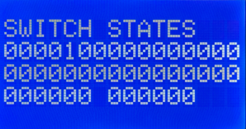
To get to the Switch States screen, press the HOME button on your MASTERCELL NGX to bring up the main menu, use the SCROLL UP and SCROLL DOWN buttons to move the cursor to Switch States and press SELECT. When the screen opens, you will see a series of digits arranged across four rows.

Each digit represents one switch input on your MASTERCELL NGX. The rule is simple. A 0 means that input is off. A 1 means that input is on.

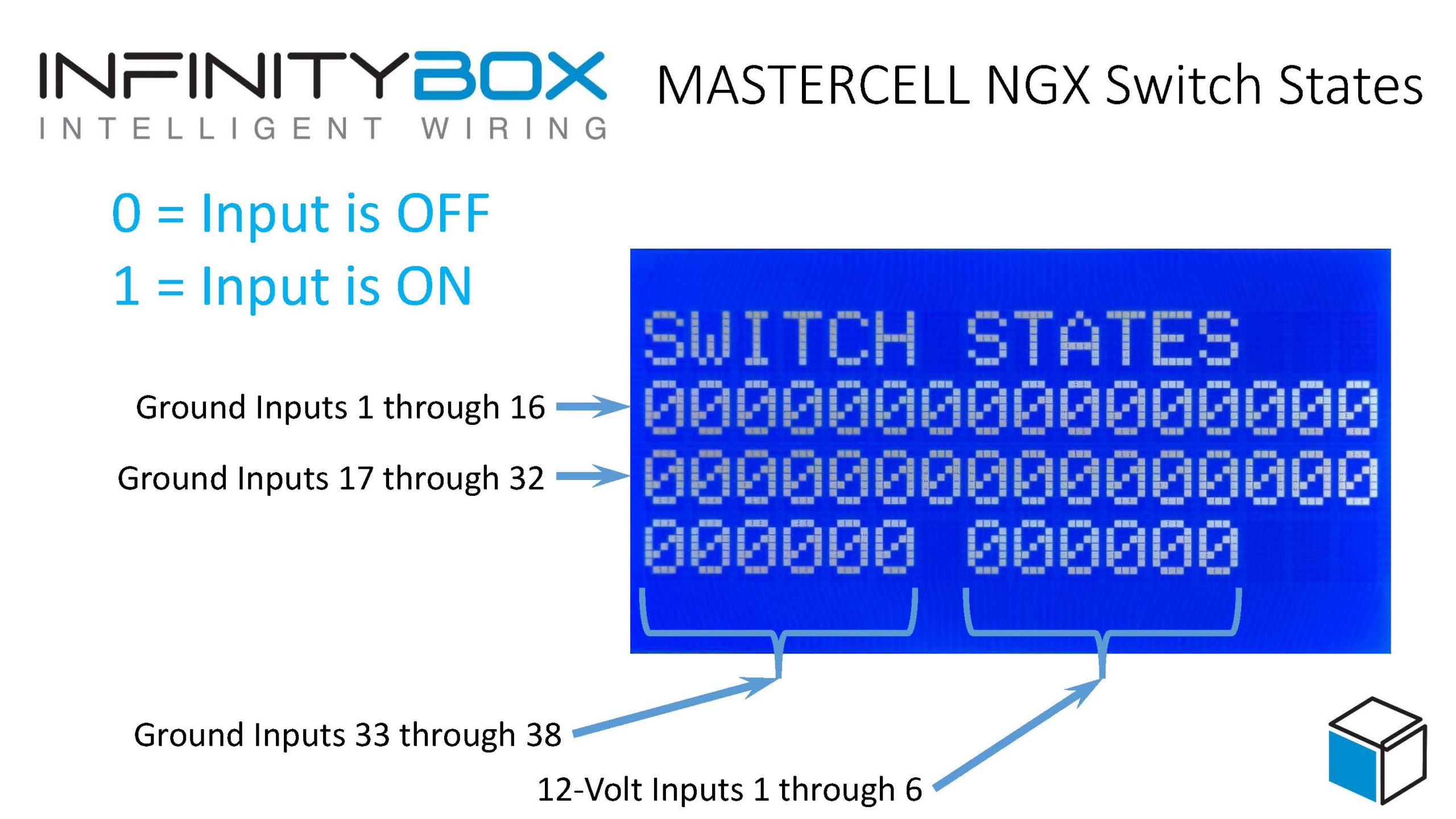
Labeled MASTERCELL NGX Switch States diagram identifying ground inputs 1 through 38 and 12-volt inputs 1 through 6 on the inSIGHT display.

MASTERCELL NGX Switch States, with callouts identifying each row of inputs and the 0 = OFF, 1 = ON legend.

The MASTERCELL NGX has 38 ground-switched inputs and 6 high-side switched inputs. The digits are laid out so that you can find any input quickly:

  • The top row shows ground-switched inputs 1 through 16.
  • The next row shows ground-switched inputs 17 through 32.
  • The bottom row shows ground-switched inputs 33 through 38 on the left.
  • After a gap, the right side of the bottom row shows the 6 high-side switched inputs, 1 through 6.

A quick note on terminology. We label the high-side switched inputs as 12-volt inputs on the screen and on your configuration sheet. Our customers use the terms “high-side switched input” and “12-volt input” interchangeably. They mean the same thing: an input that turns on when it sees 12 volts, rather than a ground. We will use 12-volt inputs through the rest of this post to match what you see on your screen.

When you are in the Switch States mode, the backlight on the inSIGHT screen will remain on.  When you are done monitoring the Switch States, you can press and release the HOME button to get back to normal operation.

Ground-Switched and 12-Volt Inputs

The MASTERCELL NGX reads two kinds of switch inputs, and the Switch States screen shows you both.

A ground-switched input turns on when it is connected to ground. This is how most of the switches in your car work with our Infinitybox system. When you flip a headlight switch, you connect the MASTERCELL NGX input to ground and the input turns on.

A 12-volt input turns on when it sees 12 volts. These are useful for connecting to devices that put out a 12-volt signal, like the fuel pump or cooling fan trigger from an EFI system. With our legacy MASTERCELL, you needed an external inVERT Mini to flip a 12-volt signal into a ground before the MASTERCELL could read it. The MASTERCELL NGX reads these 12-volt signals directly, so the inVERT Mini is no longer needed for these inputs. The Switch States screen shows you the state of both your ground-switched and 12-volt inputs in one place.

Watching the Screen in Real Time

The real power of the Switch States screen is that it updates live. As a switch turns on or off, you will see its digit change on the screen. There can be a lag of up to one second between flipping a switch and seeing the digit change, so give it a moment.

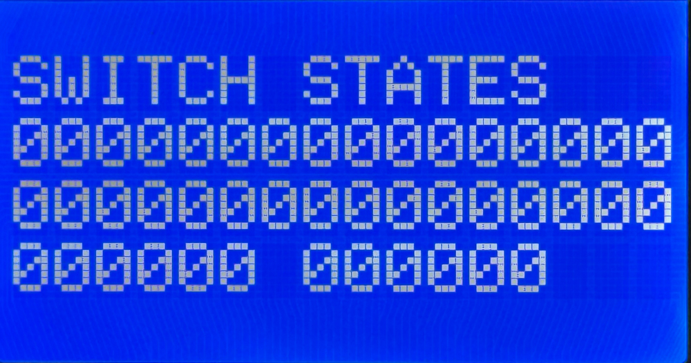
When all of your switches are off, every digit on the screen reads 0.

MASTERCELL NGX Switch States screen showing all inputs off, with every digit reading 0.

The Switch States screen with all inputs off. Every digit reads 0.

Now turn on one switch. In this example, we turned on the switch wired to ground-switched input 5. Watch the fifth digit in the top row. It changes from a 0 to a 1, while every other digit stays at 0.

MASTERCELL NGX Switch States screen showing one ground input turned on, with a single digit reading 1.

The Switch States screen with one input on. The digit for that input changes from 0 to 1.

To know which function each numbered input controls, refer to your configuration sheet. The configuration sheet is the single source of truth for which switch connects to which input on your MASTERCELL NGX. For example, on the standard front-engine configuration, input 5 is your headlights and input 6 is your parking lights. You can see an example of the standard front-engine configuration sheet by clicking this link. Always check the configuration sheet that came with your kit, since your assignments may be different if you have a custom configuration.

Wire and Test Your Switches Before Connecting Your Loads

One of the most useful things about the Switch States screen is that it lets you wire and test every switch in your car without connecting anything to a POWERCELL.

Because the MASTERCELL NGX reads your inputs directly, you can work through your entire car one switch at a time. Wire a switch, flip it, and watch the screen confirm that the MASTERCELL NGX sees it turn on and off. You can verify your entire switch harness is correct before you ever power up a load. This lets you break your wiring project into smaller, more manageable steps and confirm each one as you go.

Track Down Problems with Switch States

The Switch States screen is also a powerful diagnostic tool when something in your car is not working the way you expect.

A question we hear often is, “Why are my parking lights on?” The Switch States screen answers this quickly. Open the screen and look at the digit for your parking light input. If that digit reads 1 when the parking light switch is off, then the MASTERCELL NGX is seeing that input turn on for some reason.

In most cases, this points to one of two things. Either the switch is wired incorrectly, or the input wire is shorted to ground somewhere in your car. Because a ground-switched input turns on when it sees ground, a wire that is accidentally pinched, chafed or shorted to ground will turn that input on just as if you had flipped the switch. The Switch States screen lets you see exactly what the MASTERCELL NGX sees, so you can focus your troubleshooting on the input that is misbehaving instead of guessing.

Summary

The Switch States screen on the MASTERCELL NGX inSIGHT display gives you a real-time, at-a-glance view of every ground-switched and 12-volt input on your system. Use it to wire and test your switches without a POWERCELL, to confirm your harness is correct as you build, and to track down shorts and wiring mistakes when something is not working. Paired with your configuration sheet, it is one of the fastest ways to understand and troubleshoot your Infinitybox system.

You can download a PDF copy of the MASTERCELL NGX Switch States diagram by clicking this link.

You can download the entire MASTERCELL NGX inSIGHT document by clicking this link.  This includes all the features and functions.

Keep watching our blog for more details on the menus and diagnostic functions on the inSIGHT screen. If you have any questions, give us a call at (847) 232-1991 or contact us here.

MASTERCELL NGX Main Menu

The inSIGHT LCD screen on your MASTERCELL NGX is your window into your Infinitybox system. From the main menu, you can set up key features and access a powerful set of diagnostic tools with a few simple button presses. We covered the main status screen that you see when your system powers up in a separate blog post. You can learn about the main screen and how to read your CAN, ignition and security status by clicking this link. In this post, we want to walk through the six options on the MASTERCELL NGX main menu and explain what each one does. We will follow up with separate blog posts that take a deeper dive into each option.

Please note that this blog post covers the MASTERCELL NGX in our Next Generation IPM1 Kit. These inSIGHT diagnostic tools are specific to our Next Generation hardware. If you have our Legacy 3-Cell Kit or 20-Circuit Kit, search through our blog archives for the inSIGHT diagnostic tools that came with those systems.

The MASTERCELL NGX Main Menu

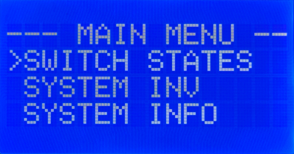
To get to the main menu, press and release the HOME button on your MASTERCELL NGX. The main menu has six options. You use the SCROLL UP and SCROLL DOWN buttons to move the cursor through the list and the SELECT button to open the option that the cursor is pointing to. Because the menu is longer than the screen, you will scroll through two views to see all six options.

MASTERCELL NGX inSIGHT main menu showing the Switch States, System Inv, and System Info options.

The top of the MASTERCELL NGX main menu, with options for Switch States, System Inv, and System Info.

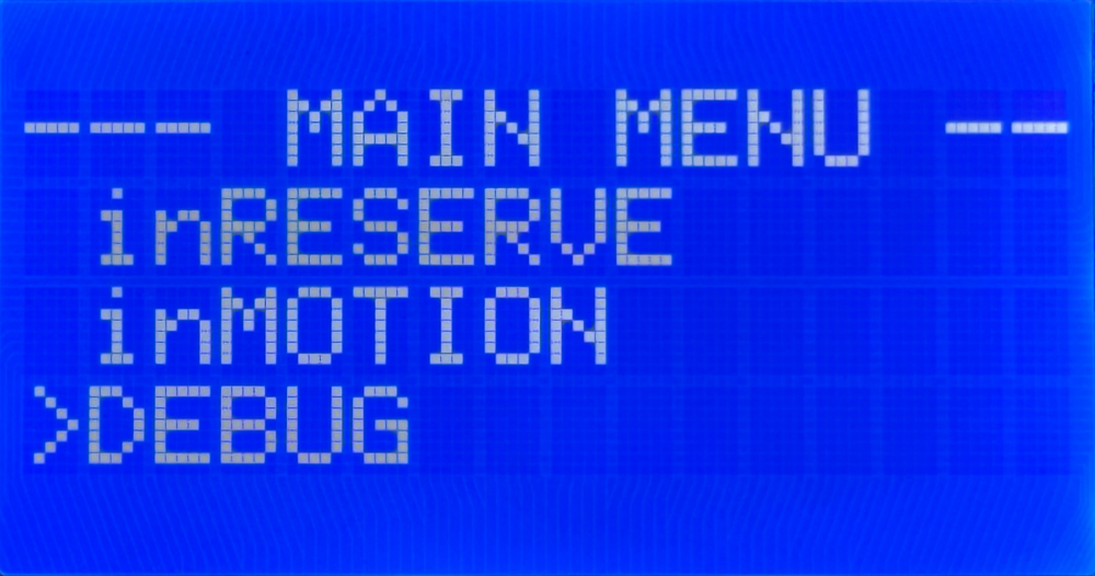
MASTERCELL NGX inSIGHT main menu scrolled to show the inRESERVE, inMOTION, and DEBUG options.

The MASTERCELL NGX main menu scrolled down to the inRESERVE, inMOTION, and DEBUG options.

The six options are Switch States, System Inv, System Info, inRESERVE, inMOTION and DEBUG. Let’s walk through each one.

Switch States

The Switch States option gives you a real-time view of every switch input on your MASTERCELL NGX. The MASTERCELL NGX has 38 ground-switched inputs and 6 high-side switched inputs. When you open Switch States, you see a screen of digits arranged across four rows. The ground-switched inputs run across the rows, and the six high-side input states appear on the right side of the bottom row. A 0 means the input is off and a 1 means the input is on. The screen updates in real time, so if a switch turns on or off while you are watching, you will see it change, with a lag of up to one second.

This is a powerful way to confirm that your switches are wired correctly. You can work through your car one switch at a time and watch the screen confirm that the MASTERCELL NGX sees each input.  Click on this link to take the deeper dive into the Switch States feature on the MASTERCELL NGX.

System Inventory

The System Inv option is your system inventory screen. It gives you a list of every peripheral connected to your MASTERCELL NGX. This can include POWERCELLs, inMOTION Cells, inVIEW Cells and inCONTROL knobs. Each device shows up with its CAN address and a name so you can confirm that the MASTERCELL NGX sees everything in your network.

You can use the SCROLL UP and SCROLL DOWN buttons to highlight a device in the inventory and the SELECT button to dig deeper into it. From there, you can see details like the state of its outputs, its voltage and more. Click here for more details on the System Inventory function.

System Info

The System Info option lets you see the software revision of the code loaded onto your system. It also shows you the configuration that is loaded. The IPM1 Kit has options for a front-engine configuration and a rear-engine configuration, along with the option for a Custom configuration. If your system shows a Custom configuration and you have questions about it, contact our technical support team for more information. You can learn more about how to read the software revision and the loaded configuration by clicking this link.  

inRESERVE

The inRESERVE option lets you set up our inRESERVE Active Battery Management accessory. inRESERVE connects a POWERCELL output to a special latching solenoid and monitors your battery voltage. When the ignition is off and the voltage drops below a set threshold for a period of time, the POWERCELL pulses the solenoid and disconnects power to the system. This proactively eliminates drain from your battery.

Every IPM1 Kit ships without inRESERVE set up. If you purchase the inRESERVE option, this menu lets you enable the feature, pick the POWERCELL and output that control the solenoid, and choose the timing and voltage threshold. We have an existing blog post that walks through this whole process. You can learn how to enable inRESERVE on your MASTERCELL NGX by clicking this link.

inMOTION

The inMOTION option walks you through the process of setting up your inMOTION NGX door modules. inMOTION NGX installs in the door, and each module must be set with its proper address so it knows which commands to obey. The default locations are Driver Front, Passenger Front, Driver Rear and Passenger Rear. You order as many inMOTION NGX modules as you need for your build, two for a 2-door car or four for a 4-door car. We ship them set up generically, so you run this process once to tell each module where it is installed in the car. You can learn how to configure your inMOTION NGX door modules by clicking this link.

DEBUG

The DEBUG option puts the MASTERCELL NGX into what we call Messaging Mode. Where Switch States shows you whether an input is on or off, Messaging Mode goes a step deeper. It displays in real time when the MASTERCELL NGX sees an input turn on or off, and then shows you what the MASTERCELL NGX does in response.

This is a powerful tool for confirming that your switches are wired correctly and that your MASTERCELL NGX is programmed the way you expect. For example, if your headlights are not working, you can put the MASTERCELL NGX into Messaging Mode and turn the headlight switch on. The inSIGHT screen will display the input it saw turn on and confirm which POWERCELL and which output it is commanding to turn on. We will take a closer look at Messaging Mode in its own blog post.

Summary

The main menu on the MASTERCELL NGX inSIGHT display is your gateway to the setup and diagnostic functions built into your Next Generation Infinitybox system. From these six options, you can check your switches, review your system inventory, see your software and configuration, set up inRESERVE, configure your inMOTION NGX modules and dig into advanced diagnostics with Messaging Mode. Keep watching our blog as we publish a detailed deep dive into each one.

You can download the entire MASTERCELL NGX inSIGHT document by clicking this link.  This includes all the features and functions.

Give us a call at (847) 232-1991 or contact us here if you have any questions.

MASTERCELL NGX Main Screen

The inSIGHT LCD screen on your MASTERCELL NGX is your window into your Infinitybox system.  With a few simple button presses, the screen lets you set up your IPM1 kit plus gives you powerful diagnostic tools.  We’ve talked about the features under the cover of your MASTERCELL NGX in a separate blog post.  You can learn about the inSIGHT screen, the menu buttons and other features by clicking this link.  In this post, we want to talk about the main screen on your MASTERCELL inSIGHT screen.  Please note that this blog post discusses the MASTERCELL NGX in our Next Generation IPM1 kit.  If you have our Legacy 3-Cell Kit or 20-Circuit Kit, search through our blog posts for details.

MASTERCELL NGX HOME Screen

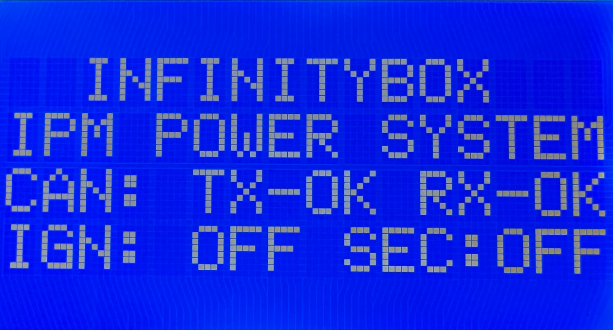
After your IPM1 kit powers up, you will see this screen on your MASTERCELL.

Main status screen on the MASTERCELL NGX inSIGHT display showing CAN bus status and ignition state

The main status screen on the MASTERCELL NGX inSIGHT display.

The backlight on the screen will remain on for 5 to 10 seconds then will turn off to reduce power drawn from the battery.  To return to this screen at any time, you can press and release the HOME button.

This screen gives you several important pieces of information about your Infinitybox system.  First, it tells you the status of the CAN network.  Second, it tells you the state of ignition.  Lastly, it tells you the state of security.

CAN Status

Your Infinitybox system is connected together using a J1939 CAN network.  This is a simple 2-wire system that connects your MASTERCELL to your POWERCELLs, to your inMOTION NGX cells, to your inVIEW and to any other devices connected in your car.  At a high-level, the main screen shows you the status of the CAN network.  It shows the status of the transmit circuit (TX) and the receive circuit (RX).  You will see OK for both TX and RX when the system is communicating correctly.  If you see ERR for either TX or RX, you should check your CAN cables to make sure they are connected correctly.  You should also make sure that you have the terminator resistor that came with your IPM1 kit correctly plugged into your system.  Check your IPM1 manual for more details on the termination resistor.  If you are seeing ERR for either TX and RX, contact our technical support team by clicking this link.

Ignition State

The next important thing that the main screen displays is the state of ignition.  When the ignition is on, you will see IGN: ON.  When the ignition is off, you will see IGN: OFF.  This monitors the ignition from either the switched ignition input, the one-button start input or ignition control from inTOUCH.  Specific functions in the system can be controlled with ignition.  The most common example is turn signals.  Out of the box, the system is set so that your turn signal inputs will only work when the ignition is on.  Using our inCODE NGX tool you can set other functions to be dependent on the state of ignition.  Check out the inCODE NGX details to learn more.

Security State

The last important piece of information on the main screen is the state of security.  You will see SEC: OFF when security is disabled and SEC: ON when security is enabled.  Security can be enabled and disabled from the inLINK Key Fobs and from the inTOUCH feature on inLINK.  Out of the box, the system blocks the ignition, starter and fuel pump when security is enabled.  This is a very powerful immobilizer for your car that is built into your IPM1 kit with inLINK NGX.  Using the inCODE NGX software tool, you can set other functions in the Infinitybox system to be disabled when security is enabled.  The main screen gives you a quick and simple way to check whether security is on or off.

Summary

The main screen on the inSIGHT LCD display on the MASTERCELL NGX gives you a quick snapshot of the health of the network, the state of ignition and the state of security.  Keep watching our blog for more details of the menus and functions on inSIGHT in our Next Generation System.

You can download the entire MASTERCELL NGX inSIGHT document by clicking this link.  This includes all the features and functions.

Give us a call at (847) 232-1991 or contact us here if you have any questions.

Greenworks 10.1" touchscreen mounted in a truck center console, connected to an Infinitybox IPM1 Kit

Connect a Custom Touchscreen to Your IPM1 Kit

Some of our customers want to do more than wire up a set of switches. They want to build their own way to control their Infinitybox system — a custom interface, a custom dashboard, their own logic — and make their vehicle truly one of a kind. The Next Generation IPM1 Kit was designed to welcome exactly that kind of creativity.

The entire Next Generation System runs on J1939, the same robust CAN protocol trusted across the heavy-duty and commercial vehicle world. We publish the J1939 messages that command the MASTERCELL NGX, POWERCELL NGX, inMOTION NGX and inVIEW modules, which means a builder who wants to create their own controller has a clear, documented path to do it. Want to drive the system from a touchscreen? A custom panel? Something no one has tried yet? The door is open.

Here is a customer who walked right through it.

A Builder-Designed Touchscreen Console

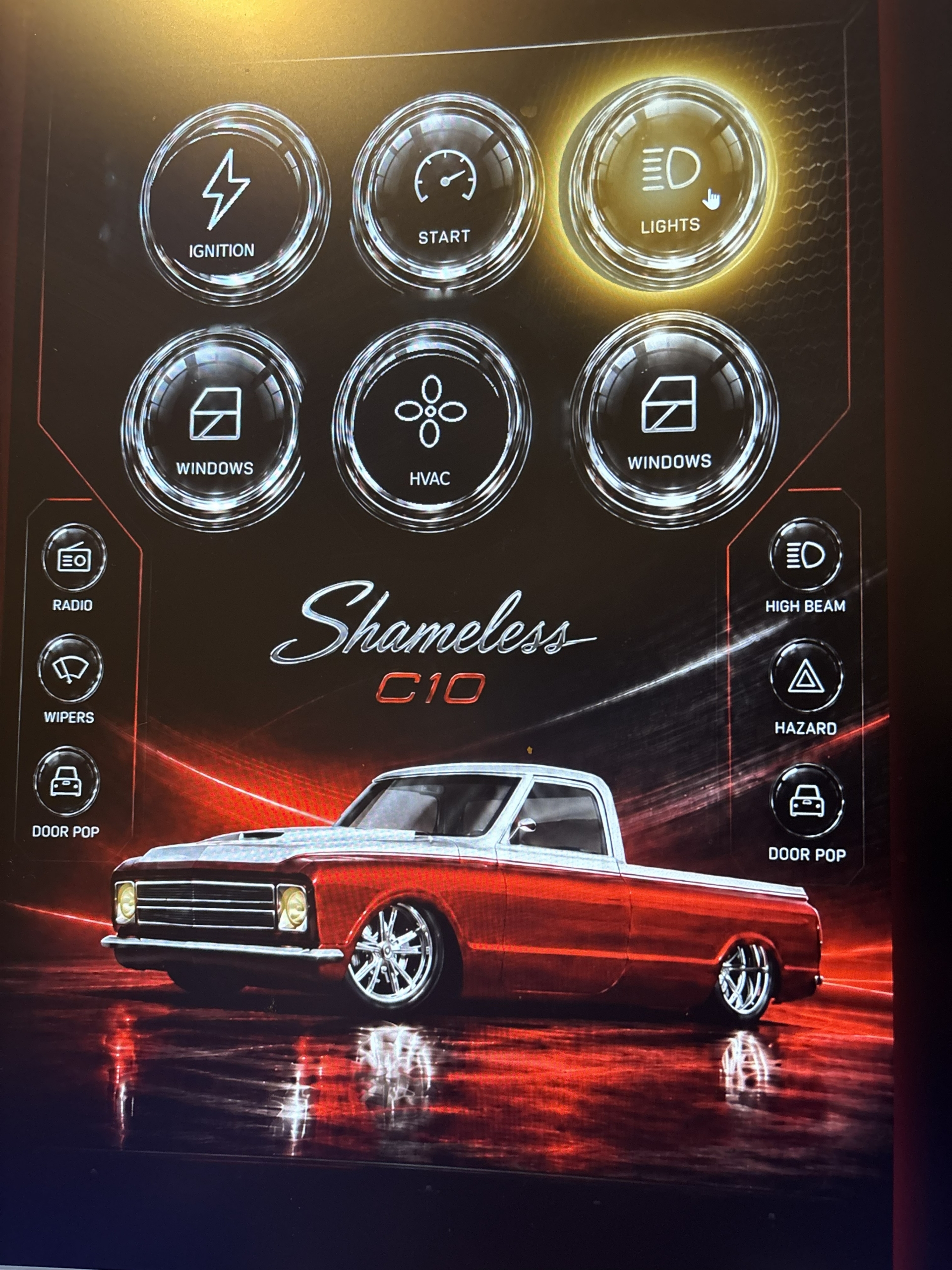
Custom touchscreen interface for the IPM1 Kit showing controls for windows, ignition, starter, and lighting

The custom touchscreen interface for “Shameless,” a 1967 C10, with controls for windows, ignition, starter, and lighting.

Brook B. at White Post Restorations wanted something clean, modern, and entirely his own for the center console of a truck build. So he designed it — a portrait-mounted 10.1″ Greenworks touchscreen running on a Raspberry Pi, with a custom interface he created to control the vehicle’s electrical system.

The result is elegant. Tap an element on the screen, and the corresponding function comes to life through his Infinitybox system. No bank of physical switches. No cluttered dash. Just a sleek, intuitive display that looks like it belongs in a vehicle costing many times more.

How He Connected It

This is where the open architecture of the IPM1 Kit shines. Brook had more than one path available to him, and that flexibility is the whole point.

He chose to drive the inputs on his MASTERCELL NGX directly, using an MCP23017 I/O expander on a development board. The touch elements on his screen trigger the expander, the expander drives the MASTERCELL NGX inputs, and the system responds. Clean and direct.

Another option would have been a CAN hat for the Raspberry Pi, connecting straight to our J1939 network and sending messages directly to the system. Both approaches work. Both are open to any builder. The choice comes down to what fits your project best — and that is precisely the freedom we want our customers to have.

The Role of AI

Here is the part that would have sounded like science fiction a few years ago. Brook used AI tools to help write the code that builds his screens and controls the entire system. He did not need to be a career software engineer. He had a vision, a set of modern tools, and a system designed to be controlled — and he brought it all together.

This is the new world opening up for builders. Affordable, powerful platforms like Raspberry Pi and Arduino, combined with AI-assisted coding, are putting custom vehicle control within reach of anyone willing to experiment. Pair those tools with a system that was built to be controlled, and the creative possibilities multiply.

This Is What Flexibility Looks Like

We did not build Brook’s touchscreen. He did. We simply built a system flexible enough to say yes to it.

That is the philosophy behind the entire Next Generation System: flexibility, functionality, and simplicity. Give builders a solid, reliable foundation, publish the messages that control it, and then get out of the way so they can create.

Brook’s console is one example. Yours could be the next.

Ready to Build Something of Your Own?

If you are dreaming up a custom way to control your vehicle — a touchscreen, a custom controller, an integration we have not even thought of yet — start with the IPM1 Kit. Then reach out to us. We are always happy to talk through the options for expanding how you control your car.

Get your IPM1 Kit today, and let’s see what you build.

Call us at (847) 232-1991 or visit infinitybox.com to get started.

Wiring the Cooling Fan with the IPM1 Kit

Table of Contents

Overview

Your Infinitybox IPM1 Kit makes it easy to control your cooling fan. The MASTERCELL NGX takes the trigger signal from your temperature switch or ECU. It sends a command over the CAN network to the front POWERCELL to turn the cooling fan on and off. The POWERCELL has the switching and fuse protection built in. This eliminates the need for an external relay and a separate fuse for your cooling fan circuit.

The POWERCELL also soft-starts the cooling fan motor. This reduces the in-rush current when the fan first turns on. Soft-starting lets you drive a larger fan with a smaller gauge of wire. Click here to learn more about the benefits of soft-starting.

There are two main ways to trigger your cooling fan with the MASTERCELL NGX. You can use a traditional thermostatic switch or you can use the trigger from your ECU. The MASTERCELL NGX accepts both ground-switched and high-side switched (12-volt) inputs. This gives you the flexibility to handle either type of trigger without adding external components.

Before you go any further, check the configuration sheet that came with your IPM1 Kit. Your configuration sheet is the single point of truth for the wire colors and connector locations in your system. It will tell you which MASTERCELL NGX input is assigned to your cooling fan and which POWERCELL output drives the fan motor.

Wiring a Thermostatic Switch

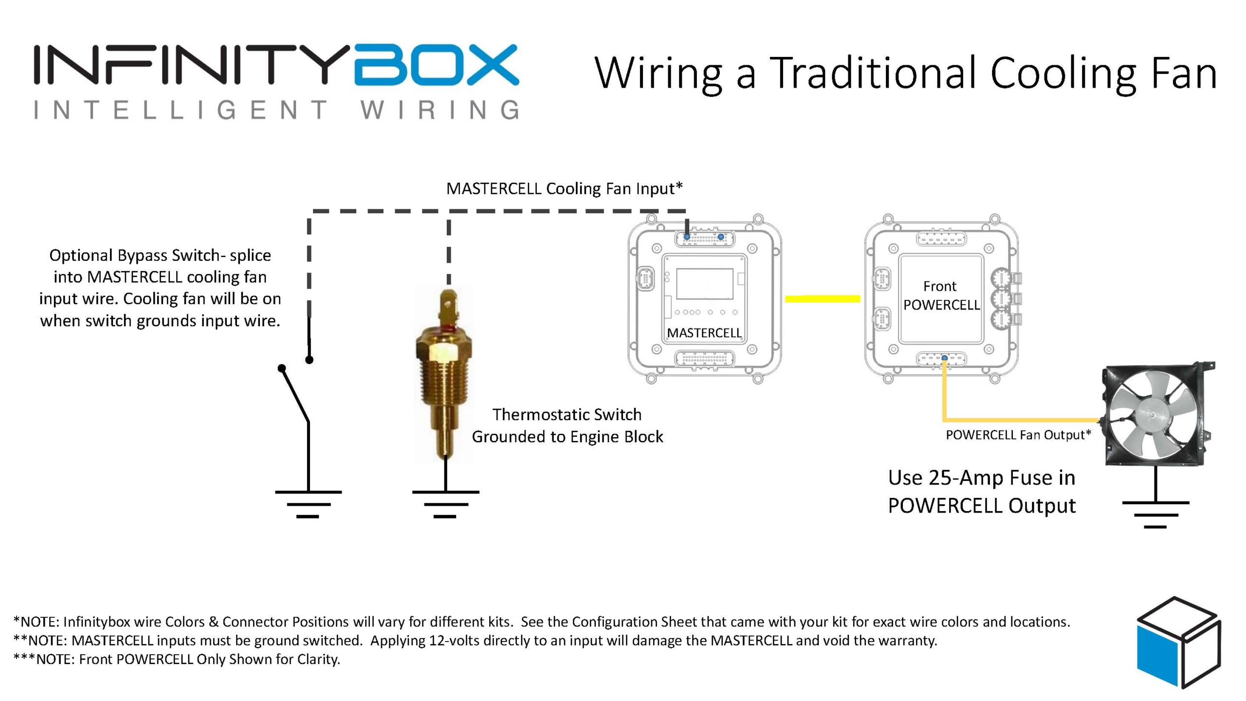
The most common way to trigger your cooling fan is with a thermostatic switch. This is a temperature-activated switch that is usually threaded into your radiator or your engine. Inside the switch, there is a bi-metal element that is set for a specific temperature. When the coolant temperature exceeds that set point, the switch closes internally and connects its terminal to ground. When the coolant temperature drops below the set point, the switch opens and disconnects from ground.

This is a ground-switched signal. You are going to connect the MASTERCELL NGX input for your cooling fan directly to the terminal on the thermostatic switch. When the switch closes, it will ground the MASTERCELL NGX input. The MASTERCELL NGX sees this change and sends a command to the front POWERCELL to turn on the cooling fan output. When the switch opens, the MASTERCELL NGX sends a command to turn the output off.

There are two common types of thermostatic switches. The most common type has a single quick-disconnect terminal. This type of switch grounds through its metal body when it threads into the radiator or the engine. You connect the MASTERCELL NGX input wire to that terminal.

The second type has two terminals. Both terminals are isolated from the metal body of the switch. You connect the MASTERCELL NGX input to one terminal and connect the other terminal to ground.

Image of wiring diagram showing how to wire a thermostatic cooling fan switch to the Infinitybox MASTERCELL

Image of wiring diagram showing how to wire a thermostatic cooling fan switch to the Infinitybox MASTERCELL

Here is an important note about temperature switches and temperature senders. There is a big difference between them. A temperature switch turns on and off at a set temperature. A temperature sender is a variable-resistance device that controls your temperature gauge. You cannot connect your cooling fan input on the MASTERCELL NGX to your temperature sender. They are two separate devices with two separate functions.

Wiring the Cooling Fan Trigger from an ECU

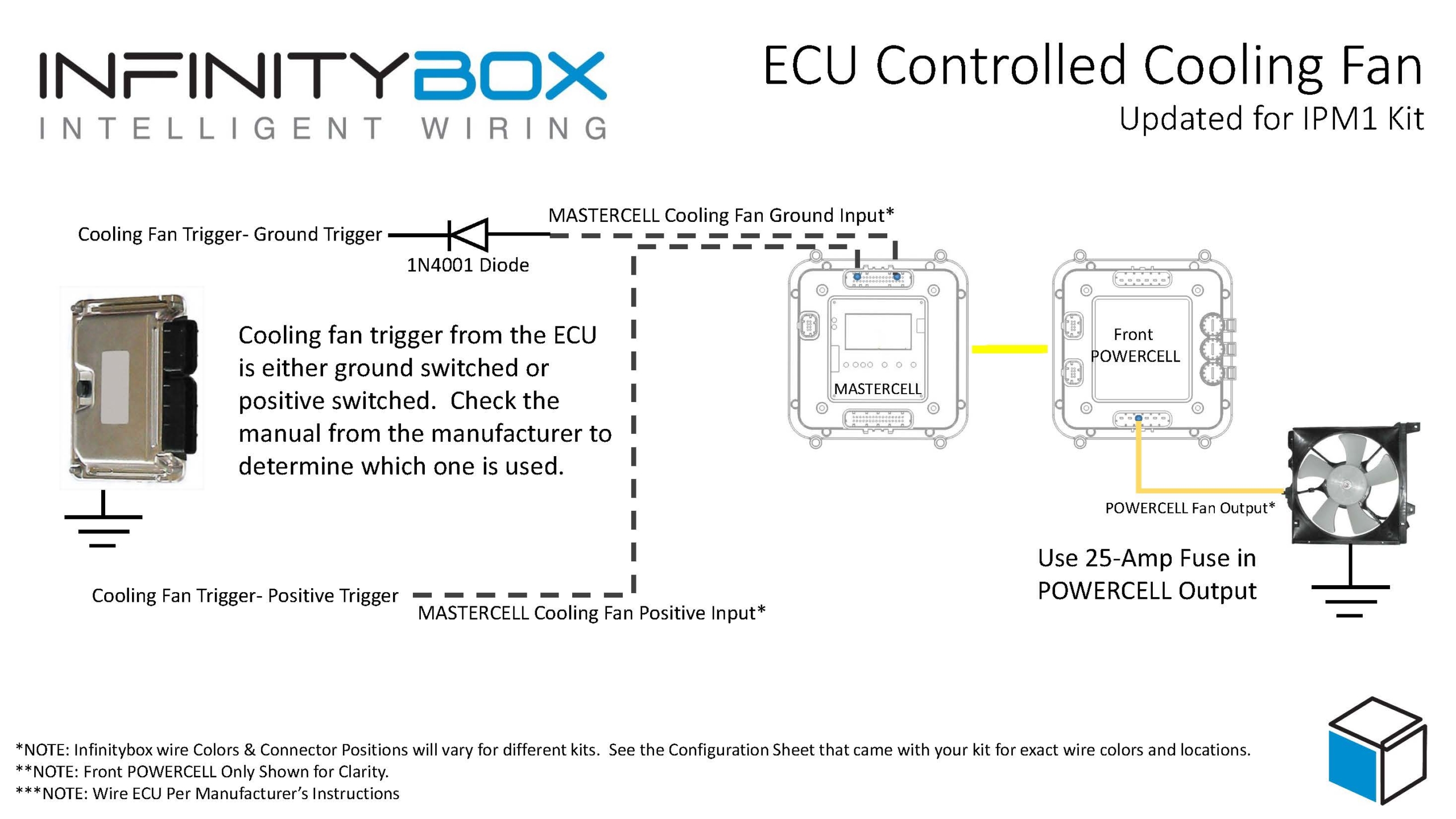
Many modern ECUs and EFI systems have a dedicated output to trigger the cooling fan. The ECU monitors the engine coolant temperature through its own sensor and decides when to turn the fan on and off. If your ECU has this capability, you can wire its cooling fan trigger directly to the MASTERCELL NGX instead of using a thermostatic switch.

The important thing to understand is whether your ECU has a ground-switched trigger or a 12-volt (high-side switched) trigger. Check the manual for your ECU to determine which type of trigger it has. The MASTERCELL NGX can handle both types of triggers natively.

Wiring diagram showing how to wire a thermostatic cooling fan switch to the MASTERCELL NGX in the Infinitybox IPM1 Kit

This diagram shows the connections between the thermostatic cooling fan switch, the MASTERCELL NGX, and the front POWERCELL in the Infinitybox IPM1 Kit.

Ground-Switched Trigger from ECU

If your ECU has a ground-switched cooling fan trigger, it internally connects the trigger wire to ground when it wants the fan on. You are going to connect this trigger to a ground-switched input on the MASTERCELL NGX.

We always recommend isolating any ground-switched input from an external system like an ECU with a 1N4001 diode. The reason is that we do not know what the ECU does with its trigger when it is off. It may let the trigger voltage float or it may pull the trigger up to battery voltage. Either of these conditions could cause erratic behavior on the MASTERCELL NGX input. To isolate the input, solder a 1N4001 diode in series between the MASTERCELL NGX input and the cooling fan trigger wire on the ECU. Install the diode with the anode facing the MASTERCELL NGX. The orientation of this diode is critical and the system will not work correctly if the diode is wired backwards.

12-Volt Trigger from ECU

If your ECU has a 12-volt cooling fan trigger, it outputs battery voltage on the trigger wire when it wants the fan on. You are going to connect this trigger to one of the high-side switched inputs on the MASTERCELL NGX.

The MASTERCELL NGX has the ability to accept 12-volt input signals directly on its high-side switched inputs. There is no need for an inVERT Mini or any other external component to flip this signal. This is one of the key advantages of the MASTERCELL NGX in your IPM1 Kit.

Adding a Bypass Switch

You may want to add a bypass switch that lets you turn on the cooling fan manually at any time. This is usually a simple toggle switch on the dash. It gives you the ability to turn the fan on even when the engine is not up to temperature.

To wire a bypass switch, connect a MASTERCELL NGX ground-switched input to one terminal on the toggle switch. Connect the other terminal to ground. You can assign this to the same cooling fan output on the POWERCELL through your inCODE NGX configuration. When you flip the switch, it grounds the MASTERCELL NGX input and turns on the cooling fan regardless of the state of your thermostatic switch or ECU trigger.

Check your configuration sheet for the specific input assigned to your bypass switch.

Wiring the POWERCELL Output to the Cooling Fan

Once you have the trigger side wired to the MASTERCELL NGX, you need to wire the output side. Connect the cooling fan output on your front POWERCELL to one wire on the cooling fan motor. Connect the other wire on the cooling fan motor to a good chassis ground. Make sure you have a solid metal-to-metal connection with no paint, grease, powder coating, or dirt in the way.

We recommend using a 25-amp fuse in the POWERCELL output to protect the wiring between the POWERCELL and the fan motor. Check your configuration sheet for the specific output and wire color for your cooling fan.

Resources

Our resources section has wiring diagrams for many different ECU and EFI systems. These show the specific connections between the ECU and the MASTERCELL NGX for the cooling fan trigger, fuel pump trigger, and ignition power. Check the blog on our website for your specific ECU.

Click here to contact our team or call us at (847) 232-1991 with any questions about wiring your cooling fan with the IPM1 Kit.

Wiring Dakota Digital GRFX Gauges with the IPM1 Kit

Table of Contents

Overview

Dakota Digital has been in the business of making advanced electrical products for the automotive aftermarket for a long time. Their products include gauges, lighting, cruise control systems, gear indicators, linear actuators, climate control interfaces and other automotive accessories. Their GRFX series represents the latest in their electronic dashboard technology. The GRFX system features full-color TFT displays with user-configurable layouts, themes and colors. A lot of our customers have asked about how to connect their GRFX controller box to our Infinitybox system. This blog post is going to walk you through the details of wiring Dakota Digital GRFX gauges with the IPM1 Kit featuring the MASTERCELL NGX.

This post is specific to our IPM1 Kit with the MASTERCELL NGX. If you have our legacy 20-Circuit Kit or our 3-Cell Kit, the wiring connections are different.

Before we go too far, this post is only going to cover wiring primary power, ground, key-on power, gauge illumination and the signals for the indicators on the dash. Their manual will cover the details for the rest of the wiring. If you are using the VHX or RTX gauges, we have separate posts covering those systems.

The big advantage of the IPM1 Kit is how the MASTERCELL NGX simplifies these connections. The MASTERCELL NGX has built-in low-current indicator outputs. In most installations, the MASTERCELL is located behind the dash — right where the Dakota Digital GRFX controller box is also located. With the IPM1 Kit, you can connect the MASTERCELL NGX indicator outputs directly to the GRFX controller without running wires back to the front POWERCELL. This is a significant wiring simplification compared to the legacy 20-Circuit Kit.

Important: The indicator outputs on the MASTERCELL NGX are limited to 1 amp each. The Dakota Digital documentation shows that the IGNITION PWR terminal on the GRFX controller draws less than 1 amp, which means it can be connected directly to a MASTERCELL NGX output. The turn signal indicators, high-beam indicator and gauge illumination outputs are designed to drive low-current loads. Do not connect anything else to these outputs that could push the total current draw over the 1-amp threshold.

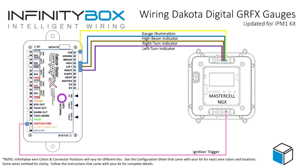
This diagram shows an overview of the connections from the MASTERCELL NGX to the GRFX controller box.

Picture of wiring diagram showing how to wire Dakota Digital GRFX Gauges with the Infinitybox IPM1 Kit featuring the MASTERCELL NGX

Wiring diagram showing how to wire the Dakota Digital GRFX Controller Box to the Infinitybox IPM1 Kit.

Constant Power and Ground

The GRFX controller needs constant power from the battery. Connect the 12 VDC CONSTANT terminal on their controller box directly to the positive terminal on the battery. You must fuse this wire at the battery for safety. Dakota Digital recommends a fused 5 to 20 amp circuit for this connection.

You also have to connect the GROUND terminal on their controller box to a good chassis ground connection. This must be a metal-to-metal connection that is free of paint, powder coating, dirt and debris.

Key-On Power

The GRFX controller box needs ignition or key-on power. This is what turns the gauges on when you turn the key in the car. With the IPM1 Kit, your MASTERCELL NGX has a dedicated indicator output for the ignition signal. Connect this output to the IGNITION PWR terminal on the GRFX controller box.

Since the MASTERCELL NGX is located behind the dash, this connection is short and direct. You are connecting two components that are both behind the dash. With the legacy 20-Circuit Kit, this power came from the front POWERCELL ignition output and you had to run a wire from the front of the car back to the GRFX controller behind the dash.

Check the configuration sheet that came with your IPM1 Kit to confirm the specific output assignment for your ignition indicator.

Gauge Illumination

You need to connect the gauge illumination output on the MASTERCELL NGX to the DIM(+) terminal on the GRFX controller box. This will change the display colors and brightness on the GRFX gauges when you have your parking or headlights on.

Again, this is a direct behind-the-dash connection with the IPM1 Kit. The MASTERCELL NGX indicator output for the gauge illumination connects straight to the DIM(+) terminal on the GRFX controller.

Turn Signal and High-Beam Indicators

Lastly, you need to connect the MASTERCELL NGX indicator outputs for your turn signals and high-beam to their respective terminals on the GRFX controller box. Connect the left turn signal indicator output to the LEFT(+) terminal, the right turn signal indicator output to the RIGHT(+) terminal and the high-beam indicator output to the HIGH(+) terminal.

When the MASTERCELL NGX is commanding the left turn signal, the indicator output will trigger and the left turn signal indicator will flash on the Dakota Digital GRFX display. The same applies for the right turn signal and the high-beam indicator.

These are all low-current indicator signals. The MASTERCELL NGX indicator outputs are purpose-built for this type of connection.

Legacy 20-Circuit Kit vs. IPM1 Kit

With the legacy 20-Circuit Kit, all of the signals going to the GRFX controller box came from outputs on the front POWERCELL. The ignition power, parking light dimmer, turn signals and high-beam connections all required splicing into POWERCELL output wires at the front of the car and running those wires back behind the dash to reach the GRFX controller. That meant longer wire runs and more splices.

The IPM1 Kit with the MASTERCELL NGX eliminates those long wire runs. The MASTERCELL NGX has built-in low-current indicator outputs that connect directly to the GRFX controller box. Since both the MASTERCELL NGX and the GRFX controller are located behind the dash, these connections are short and direct. You get a cleaner installation with less wiring.

The constant power and ground connections remain the same in both systems. The GRFX controller still gets its constant power directly from the battery and its ground from the chassis.

Downloads and Support

You can download a PDF of this wiring diagram by clicking this link.

Our technical support team is available to answer any questions about this blog post or any other topics about wiring your car with our Infinitybox system. Click on this link to get in touch with our team.

Picture of the Dakota Digital RTX Gauges

Wiring Dakota Digital RTX Gauges with the IPM1 Kit

Table of Contents

Overview

Dakota Digital has been in the business of making advanced electrical products for the automotive aftermarket for a long time. Their products include gauges, lighting, cruise control systems, gear indicators, linear actuators, climate control interfaces and other automotive accessories. Their RTX gauge family brings classic styling with modern features to any hot-rod, street rod, resto-mod or Pro-Touring build. A lot of our customers have asked about how to connect their RTX gauge controller box to our Infinitybox system. This blog post is going to walk you through the details of wiring Dakota Digital RTX gauges with the IPM1 Kit featuring the MASTERCELL NGX.

This post is specific to our IPM1 Kit with the MASTERCELL NGX. If you have our legacy 20-Circuit Kit or our 3-Cell Kit, the wiring connections are different. Click on this link to get to the wiring diagram for the legacy system.

Before we go too far, this post is only going to cover wiring primary power, ground, key-on power, gauge illumination and the signals for the indicators on the dash. Their manual will cover the details for the rest of the wiring. If you are using the VHX or GRFX gauges, we have separate posts covering those systems.

The big advantage of the IPM1 Kit is how the MASTERCELL NGX simplifies these connections. The MASTERCELL NGX has built-in low-current indicator outputs. In most installations, the MASTERCELL is located behind the dash — right where the Dakota Digital RTX controller box is also located. With the IPM1 Kit, you can connect the MASTERCELL NGX indicator outputs directly to the RTX controller without running wires back to the front POWERCELL. This is a significant wiring simplification compared to the legacy 20-Circuit Kit.

Important: The indicator outputs on the MASTERCELL NGX are limited to 1 amp each. The turn signal indicators, high-beam indicator and gauge illumination outputs are designed to drive low-current loads like LEDs. Do not connect anything else to these outputs that could push the total current draw over the 1-amp threshold.

This diagram shows an overview of the connections from the MASTERCELL NGX to the RTX controller box.

Picture of wiring diagram showing how to wire Dakota Digital RTX Gauges with the Infinitybox IPM1 Kit featuring the MASTERCELL NGX

Wiring diagram showing how to wire the Dakota Digital RTX Gauge Controller Box to the Infinitybox IPM1 Kit.

Constant Power and Ground

The RTX controller needs constant power from the battery. Connect the 12 VDC CONSTANT terminal on their controller box directly to the positive terminal on the battery. You must fuse this wire at the battery for safety.

You also have to connect the GROUND terminal on their controller box to a good chassis ground connection. This must be a metal-to-metal connection that is free of paint, powder coating, dirt and debris.

Key-On Power

The RTX controller box needs ignition or key-on power. This is what turns the gauges on when you turn the key in the car. With the IPM1 Kit, your MASTERCELL NGX has a dedicated indicator output for the ignition signal. Connect this output to the IGNITION PWR terminal on the RTX controller box.

Since the MASTERCELL NGX is located behind the dash, this connection is short and direct. You are connecting two components that are both behind the dash. With the legacy 20-Circuit Kit, this power came from the front POWERCELL ignition output and you had to run a wire from the front of the car back to the RTX controller behind the dash.

Check the configuration sheet that came with your IPM1 Kit to confirm the specific output assignment for your ignition indicator.

Gauge Illumination

You need to connect the gauge illumination output on the MASTERCELL NGX to the DIM terminal on the RTX controller box. This will turn on the illumination on the RTX gauges when you have your parking or headlights on.

Again, this is a direct behind-the-dash connection with the IPM1 Kit. The MASTERCELL NGX indicator output for the gauge illumination connects straight to the DIM terminal on the RTX controller.

Turn Signal and High-Beam Indicators

Lastly, you need to connect the MASTERCELL NGX indicator outputs for your turn signals and high-beam to their respective terminals on the RTX controller box. Connect the left turn signal indicator output to the LEFT terminal, the right turn signal indicator output to the RIGHT terminal and the high-beam indicator output to the HIGH terminal.

When the MASTERCELL NGX is commanding the left turn signal, the indicator output will trigger and the left turn signal indicator will flash on the Dakota Digital gauges. The same applies for the right turn signal and the high-beam indicator.

These are all low-current indicator signals designed to drive LEDs. The MASTERCELL NGX indicator outputs are purpose-built for this type of connection.

Legacy 20-Circuit Kit vs. IPM1 Kit

With the legacy 20-Circuit Kit, all of the signals going to the RTX controller box came from outputs on the front POWERCELL. The ignition power, parking light dimmer, turn signals and high-beam connections all required splicing into POWERCELL output wires at the front of the car and running those wires back behind the dash to reach the RTX controller. That meant longer wire runs and more splices.

The IPM1 Kit with the MASTERCELL NGX eliminates those long wire runs. The MASTERCELL NGX has built-in low-current indicator outputs that connect directly to the RTX controller box. Since both the MASTERCELL NGX and the RTX controller are located behind the dash, these connections are short and direct. You get a cleaner installation with less wiring.

The constant power and ground connections remain the same in both systems. The RTX controller still gets its constant power directly from the battery and its ground from the chassis.

Downloads and Support

You can download a PDF of this wiring diagram by clicking this link.

Our technical support team is available to answer any questions about this blog post or any other topics about wiring your car with our Infinitybox system. Click on this link to get in touch with our team.