
Custom BMW E9
Here is another great example of what our customers can do. This car is stunning and we can honestly say that we’ve never seen another like it. John Ward of Fuel Bespoke Design in Australia just had a great article published in Silodrome magazine. The article covers the details of his stunning restoration of a 1970 BMW 2800CS lovingly named “Von Trapp”. The article covers the car in detail and the pictures are awesome. Andrew Jones shot the pictures and we heartily thank him for their use in this blog post.

Custom-BMW-E9-Left-Side wired with the Infinitybox system
John started with a pretty rough car for this project. It took a ton of body work, straightening and reinforcing to get the car to what you see today. John wanted to do this car as a true restomod: keep it original on the exterior and interior but put modern features under it. For example, he replaced the original powerplant with a modern E46 M3 3.2 litre 330HP S54 motor and the E36 M3 5-speed manual transmission.

Custom-BMW-E9-Engine wired with the Infinitybox system
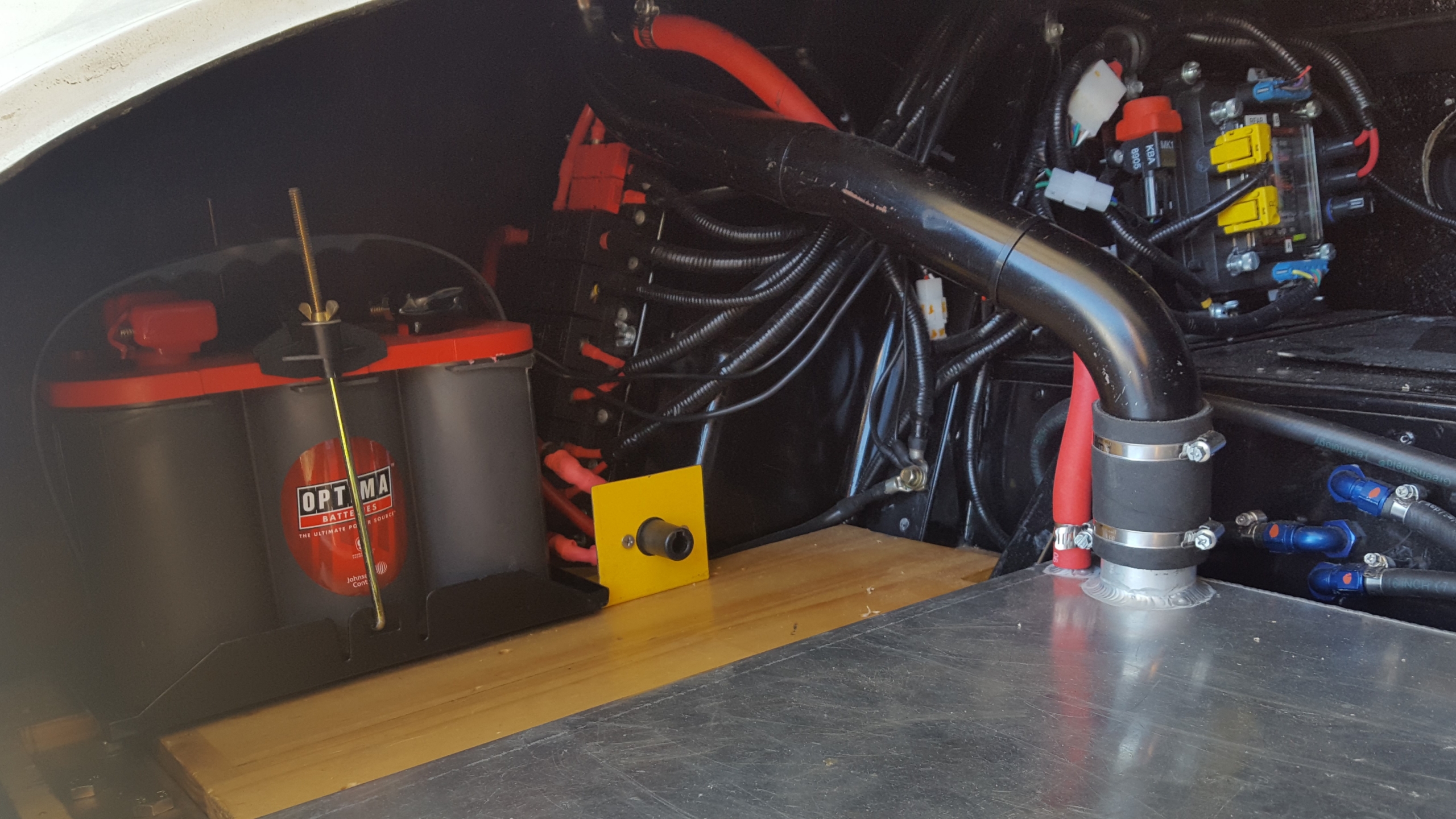
He also wanted to use the latest and greatest for his electrical and wiring system. He wired the car with our 20-Circuit Kit, with inMOTION, inLINK and inRESERVE. The end product is seamless. You can see no trace of the modern electrical system in this car. For example, check out the trunk-mounted rear POWERCELL and inMOTION cell.

Infinitybox POWERCELL and inMOTION Cell wired into a Custom-BMW-E9
When the trim piece is installed in the trunk, all traces of the electrical system disappear.
John has a detailed build history on his website. You can see all of the details on the building of “Vonn Trapp” by clicking this link.
You can also read the full article featured on Silodrome by clicking this link.
We want to extend thanks to John Ward at Fuel Bespoke Design, Ben Branch at Silodrome for the great article and Andrew Jones at Lens Flare Air for the awesome pictures.
Click on this link if you want to learn more about how you can use our Infinitybox system to wire you car or truck project.
 Copyright Infinitybox, LLC 2021. All Rights Reserved.
  Copyright Infinitybox, LLC 2021. All Rights Reserved.


 Copyright Infinitybox, LLC 2021. All Rights Reserved.


