Our inCODE Programmer is the tool that you need to load custom configurations into your Infinitybox system. It connects your computer to your MASTERCELL to let you make changes. Our technical support team makes the changes for you. You use inCODE to load these changes into your system. This link will take you to the basics on using inCODE.
If you carefully read the instructions for using inCODE, you will see a big and bold message that says to not plug the inCODE programmer into your computer until after you have loaded the Embed Inc software. When you plug the inCODE programmer into your computer, Windows automatically installs the drivers that it needs to make it work correctly. When you install the Embed Inc software, it installs the drivers for inCODE and leaves instructions for Windows so it knows what to do with inCODE. If you plug inCODE into your computer before you install the Embed Inc software, your computer takes a guess at what the inCODE programmer is and assigns a random driver to it. You will get an error when you try to load code onto your system if this happens.
Reinstalling the Embed Inc software will not solve this issue since Windows has already assigned the wrong driver to the inCODE hardware. You need to remove the inCODE programmer from your Device Manager and let Windows recognize it again. This quick video will help you go through this process.
inMOTION is a unique module that connects to the CAN network of your 20-Circuit Kit. It looks like a POWERCELL but acts differently. Instead of turning 10 things on and off like a POWERCELL, it reverses the polarity to 5 things. We originally designed inMOTION to control power windows and power lock actuators. Instead of relying on a switch, inMOTION has special h-bridge relays that reverse the polarity. This lets you change direction of things like power windows, power locks, linear actuators and valves.
That is just the beginning. inMOTION is smarter than a POWERCELL which means that you can get express features on your windows with no limit switches. You can also get wireless control through inLINK or a smart phone attached to inTOUCH NET.
Check out this video for a deeper dive into what inMOTION can do.
We have the solid model for the inMOTION cell available to our customers to help with their planning and mocking up process.
https://infinitybox.com/wp-content/uploads/2021/02/Infinitybox-Video-inMOTION.png7201280adminhttps://infinitybox.com/wp-content/uploads/2021/02/infinitybox-logo-https-1-1.pngadmin2019-12-12 20:38:392021-02-25 20:45:55inMOTION Video
Our inRESERVE Active Battery Management System is a great accessory for your 20-Circuit Kit. As you add more and more electrical requirements to your car, the demand on the battery increases when the car is sitting idle. inRESERVE continuously watches your battery voltage and safely disconnects the battery if it gets too low with your car is not being driven. This keeps your battery from being deep cycled and always leaves enough charge in the battery so you can get started again. Learn more about inRESERVE in this video.
https://infinitybox.com/wp-content/uploads/2021/02/Infinitybox-Video-inRESERVE.png7201280adminhttps://infinitybox.com/wp-content/uploads/2021/02/infinitybox-logo-https-1-1.pngadmin2019-12-04 20:33:192021-02-25 20:38:33inRESERVE Video
Our inLINK Wireless Control Accessory is our most popular add-on to our 20-Circuit Kit. It gets you powerful control of your car’s electrical features through a simple 4-button key fob. The inLINK accessory comes with a small radio receiver that gets installed inside your MASTERCELL. There is no external box that you need to make inLINK work. We recently published this video that shows you the details of inLINK and what it can do for your car or truck wired with our Infinitybox system. Check it out here.
https://infinitybox.com/wp-content/uploads/2021/02/Infinitybox-Video-inLINK.png7201280adminhttps://infinitybox.com/wp-content/uploads/2021/02/infinitybox-logo-https-1-1.pngadmin2019-12-03 20:28:162021-02-25 20:33:02inLINK Video
Here’s another great example of a customer car wired with our Infinitybox system. Paul L. wired this beautiful 1970 Mustang with our 20-Circuit Kit, inLINK and inMOTION. Paul just sent us pictures showing off the finished car and how he installed his Infinitybox system.
This picture shows the center console of his car. You can see the MASTERCELL and the inMOTION cell located in the frame of the center console. The MASTERCELL connects to all of his switches. The inMOTION cell controls the motion of his power windows and door locks.
MASTERCELL and inMOTION cell in a 1970 Mustang wired with the Infinitybox system
You can see in this picture how seamlessly these cells disappear into the interior of the car.
Interior of a 1970 Mustang wired with the Infinitybox system
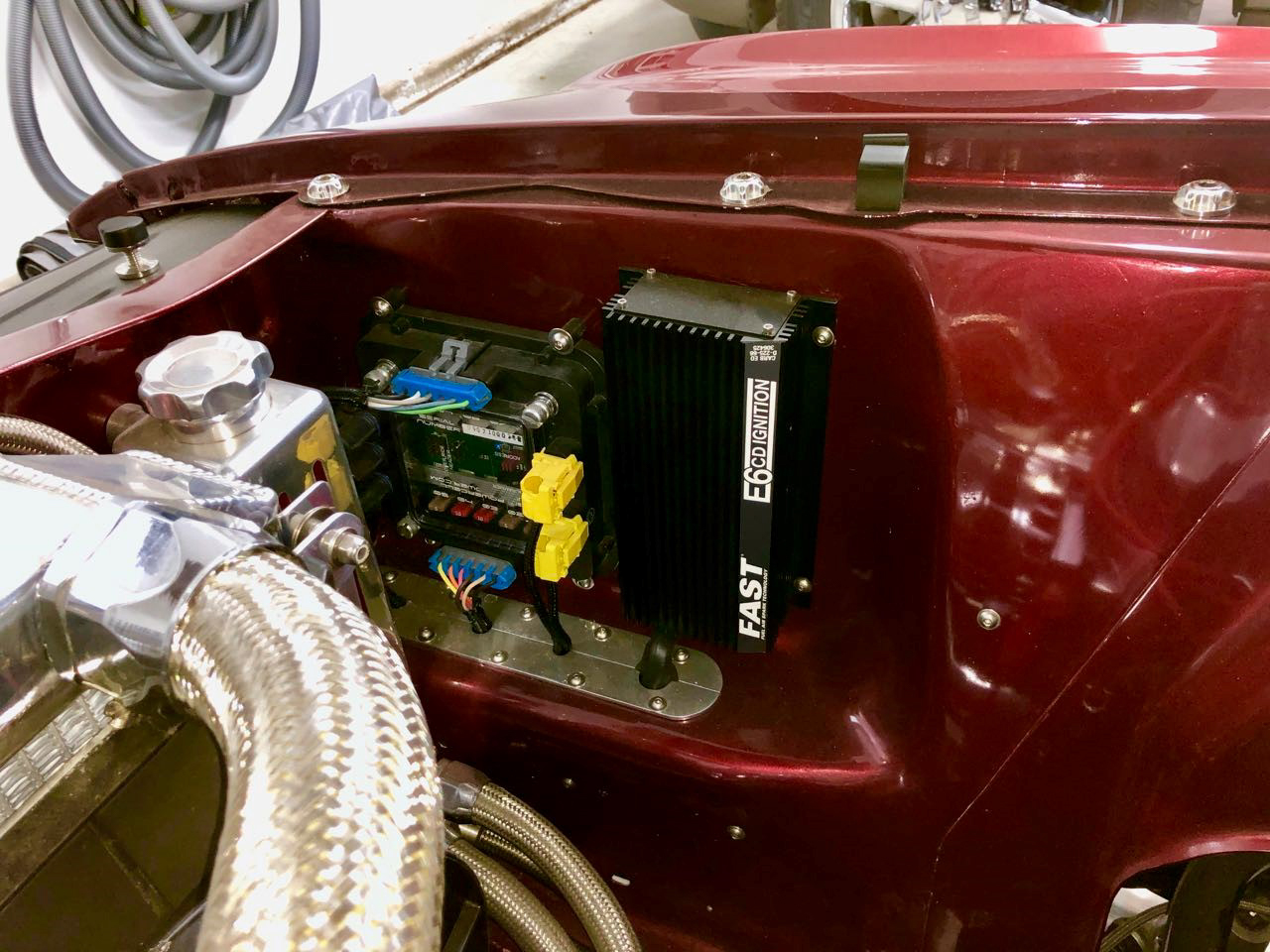
His engine looks great under the hood.
Front POWERCELL Mounted Under the Hood of a 1970 Mustang Wired with the Infinitybox System
He relocated the battery to the trunk of the car. He used this space for his ignition system and his front POWERCELL. This POWERCELL location is great because it makes most of his front wiring short and easy to install. His headlights, high-beams, turn signals, running lights, starter solenoid, ignition power, cooling fan and horn are all powered from this location.
Front POWERCELL Mounted Under the Hood of a 1970 Mustang Wired with the Infinitybox System
His rear POWERCELL is located in the trunk. This makes wiring his brake lights, turn signals, rear running lights, fuel pump, trunk popper and other accessories very easy.
We did some simple customization of this code to get him extra features. He’s controlling his door locks from outputs on inMOTION. His doors lock and unlock when he enables and disables security from his inLINK key fob. He is also using a POWERCELL output to operate a solenoid to pop his trunk. We programmed a button on his inLINK key fob to pop the trunk. He also wanted an output on his rear POWERCELL to turn on with ignition. These are all very simple changes to our system.
The finished wiring is simple and elegant. We thank Paul L. for sending these pictures. We’re proud to be a part of his project.
Our 20-Circuit Kit is the core to the electrical system in your car. It is more than just a wiring harness. It is a universal wiring system that gets you the most advanced, functional and reliable electrical control on the market. The 20-Circuit Kit starts with our MASTERCELL, which connects to your switches. It also includes two of our POWERCELLs, which we call the muscles of your system. The MASTERCELL sends commands to the POWERCELLs to locally power your lights, ignition, starter solenoid, cooling fans, fuel pumps, horn and other accessories. We’ve talked about the MASTERCELL in more detail in a recent blog post. You can link to that here. This post is going to cover more details about our POWERCELL.
The 20-Circuit Kit includes 2 POWERCELLs. Each POWERCELL can control 10-outputs. One POWERCELL is for the front of the car, the second is for the rear of the car. The front POWERCELL is set up to control your headlights, high-beams, turn signals, front running lights, horn, cooling fan, ignition power, starter solenoid and dash power. The rear POWERCELL is set up to control your rear running lights, turn signals, brake lights, fuel pump, back-up lights, dome lights and other accessories.
You put the POWERCELLs in the car were you need them. This lets you eliminate size and weight of the wiring harness in your car. The installation is simpler because the runs of wire are shorter and troubleshooting is easier.
The POWERCELL is a remote fuse and solid-state relay box. The fuses that you need to properly protect your wiring harness are built into the POWERCELL. You do not need to add separate fuses. Also, the solid-state relays that control your loads are built into the POWERCELL. Each output can carry up to 25-amps continuously so you do not need to add external relays to control your lights, fans, pumps and other accessories. Also, we don’t use mechanical relays in our POWERCELLs. Our outputs are controlled by solid-state MOSFETs. This are rugged and reliable and give you tons of benefits over traditional relays. Check out this link to learn about some of the advantages of a MOSFET.
This video walks through more of the details of the Infinitybox POWERCELL.
You can easily add extra POWERCELLs to your 20-Circuit Kit if you need to expand the output capacity beyond 20. Each additional POWERCELL gives you 10 more outputs to your Infinitybox system. The POWERCELL kit includes the POWERCELL plus all of the harnessing required to connect to your existing 20-Circuit Kit. You can learn more about the POWERCELL kit by clicking this link.
We have the solid model for the POWERCELL available to our customers to help with their planning and mocking up process.
Nu-Relics has been manufacturing power windows solutions for restorations since 2005. They pride themselves in making direct drop-in electric power windows for classic cars and trucks. Their products use the highest quality materials and are designed with the exact bolt pattern required for your project. They also use the exact same geometry for smooth and reliable power window action. They also make a very clever product called Nu-Crank. This is a switch assembly that they developed to control your power windows. The big difference from other window switches is that Nu-Crank uses the original window crank to drive the power windows up and down. You get the look of the original interior in your classic car with the convenience of power windows. The Nu-Crank mounts in the location where the original crank was located. You lift the crank to raise the power window and push down on the crank to lower it. It is very simple and elegant.
You can very easily integrate the Nu-Crank switches into our Infinitybox system to control your power windows with our inMOTION Motor Controller Cell. With our 20-Circuit Kit and inMOTION, you can control your power windows from any switch, that includes the Nu-Crank switches. The MASTERCELL inputs wire to the switches and inMOTION reverses the polarity going to the motors. It is very easy.
A customer asked us recently how if there was a way to control both the driver and passenger power windows from the driver’s side of the car without reaching over to the passenger side. The answer is yes. This can be done easily by adding a Double Pole, Double Throw (DPDT) switch to your harness. A DPDT switch has two different sets of contacts inside. It also has two switched positions. Using this DPDT switch, you can route the driver’s Nu-Crank switch contacts to two different pairs of MASTERCELL inputs. See the wiring diagram below.
Picture of wiring diagram showing how to wire the Nu-Relic Nu-Crank power window switches with the Infinitybox system
The wire colors shown in this diagram may not match the MASTERCELL inputs or inMOTION outputs for your specific system. Please reference the configuration sheet that came with your kit for exact wire colors.
You can easily hide this DPDT switch on the drivers side of the car. By flipping the switch between the driver and passenger position, you get the ability to control either power window from the driver’s switch. That way, you can control the passenger window without having to reach across the car to move the Nu-Crank switch.
Since the MASTERCELL inputs require so little current to trigger the input, you can use practically any DPDT switch. The MASTERCELL inputs require less than 1 milliamp so you do not have to worry about damaging the contacts of your DPDT switch of the contacts in the Nu-Crank switch after repeated operation.
The MASTERCELL is the brain of our Infinitybox system. It is the core of our universal 20-Circuit Kit. It connects to all of the switches in your car and decides what should be turning on and off in your electrical system. The MASTERCELL connects to the POWERCELLs, inMOTION cells and other Infinitybox accessories through our CAN network and sends commands to control everything in your car.
The Infinitybox MASTERCELL
All of your switches wire to the MASTERCELL. Examples include you headlight switch, ignition switch, brake pedal switch and turn signal stalk. You can even connect the MASTERCELL inputs to your ECU directly to take signals to control your cooling fans and fuel pump. The MASTERCELL inputs work by being grounded to turn the input on. There is no power at the switch. Instead of having to bring power to the switch, you simply connect the MASTERCELL input to one terminal of the switch and you ground the other side of the switch. When the switch is turned on, the MASTERCELL input gets connected to ground. The MASTERCELL sees this ground signal and sends the commands to turn things on and off on the POWERCELLs. Check out this blog post for a more detailed description of how the MASTERCELL inputs work.
The MASTERCELL also has the capability to include our optional inLINK radio. This accessory gets you remote control of your Infinitybox system through a key fob. You can control your lights, pop your trunk and access our power security and immobilizer features by pushing a button. The receiver for the inLINK radio gets installed inside the MASTERCELL so there is no separate box that you need to install, wire or conceal. This link will take you to more details on inLINK.
Our Infinitybox 20-Circuit Kit is a universal wiring harness. You can wire practically any street rod, resto-mod, restoration, hot rod, kit car or Pro-Touring car with it. It gets you all of the electrical control of lights, ECU’s, starters, fans, pumps and accessories that you need plus it gets you the capability to get the latest and greatest control of your car.
The 20-Circuit Kit is a universal wiring system that includes all of the components that you need to wire your car. It includes our MASTERCELL, two of our POWERCELLs, the primary power harnesses to connect your battery to the POWERCELLs, the primary fuses to protect these power harnesses, the output harnesses from the POWERCELLs, the input harnesses to go from your MASTERCELL to your switches and the CAN cable that connects the cells together. The kit also includes the manual for the system and the configuration sheet that is your road map to wiring your car.
The harnesses included in the kit are universal. They have the mating connector for our system on one end. The other end is a pig-tail. You run this harness to your switches or your accessories. You cut it to length and make the connection.
This video features Jay Harris, president of Infinitybox, walking through the contents of a 20-Circuit Kit.
With the 20-Circuit Kit as your electrical foundation, you can add any of our accessories to get a powerful and functional electrical system.
Be sure to subscribe to our YouTube channel and click on the bell icon so you get notified when we post new videos.
https://infinitybox.com/wp-content/uploads/2021/02/Infinitybox-Video-Whats-in-the-box.png7201280adminhttps://infinitybox.com/wp-content/uploads/2021/02/infinitybox-logo-https-1-1.pngadmin2019-11-18 16:40:052021-02-25 16:45:33What’s In The Box?
Infinitybox is excited to announce a new series of videos going through the details of our Infinitybox system. We’ve shot them in a very simple and effective way to get the point across. Jay Harris, the president of Infinitybox, will take you through every piece of our system. He will also walk you through the process to wire your car with our Infinitybox system.
In this introductory video, Jay describes how our Infinitybox system works and how it is different from traditional wiring harnesses. Until Infinitybox came onto the scene in 2009, little had changed in the way you wire a car since the Model T. Our system revolutionized the way restorations, kit cars, resto-mods, street rods, hot rods, race cars and Pro-Touring cars were wired. Instead of a single, central box of fuses and relays, the Infinitybox gives you separate modules that you put in the car where you need them. The separate Infinitybox modules are connected with a simple and thin data cable. You can watch the introductory video here.
This is the first video in the series. There are more coming that go through each of our specific products. Be sure to subscribe to our YouTube channel Infinityboxllc and click on the bell icon to get notified when we post new videos.
https://infinitybox.com/wp-content/uploads/2021/02/Infinitybox-Video-Overview.png7201280adminhttps://infinitybox.com/wp-content/uploads/2021/02/infinitybox-logo-https-1-1.pngadmin2019-11-14 16:37:162021-02-25 16:39:29Infinitybox Introductory Video
 Copyright Infinitybox, LLC 2021. All Rights Reserved.
 Copyright Infinitybox, LLC 2021. All Rights Reserved.
 Copyright Infinitybox, LLC 2021. All Rights Reserved.
 Copyright Infinitybox, LLC 2021. All Rights Reserved.
  Copyright Infinitybox, LLC 2021. All Rights Reserved.


 Copyright Infinitybox, LLC 2021. All Rights Reserved.

 Copyright Infinitybox, LLC 2021. All Rights Reserved.
 Copyright Infinitybox, LLC 2021. All Rights Reserved.
 Copyright Infinitybox, LLC 2021. All Rights Reserved.