Posts

Messaging Mode on the MASTERCELL NGX

The DEBUG option on your MASTERCELL NGX puts the module into what we call Messaging Mode. It is the deepest diagnostic tool built into the inSIGHT screen. Where the Switch States screen shows you whether an input is on or off, Messaging Mode goes a step further. It shows you what the MASTERCELL NGX does in response to that input, in real time, right on the screen. This blog post is part of our series on the diagnostic functions built into the inSIGHT screen. We introduced this option in our overview of the MASTERCELL NGX main menu, and it works hand in hand with the Switch States screen. In this post, we take a closer look at how to read and use Messaging Mode.

Please note that this blog post covers the MASTERCELL NGX in our Next Generation IPM1 Kit. These inSIGHT diagnostic tools are specific to our Next Generation hardware. If you have our Legacy 3-Cell Kit or 20-Circuit Kit, search through our blog archives for the diagnostic tools that came with those systems.

How Cases Work

To understand what Messaging Mode is showing you, it helps to understand cases. Every input on your MASTERCELL NGX has cases assigned to it. These cases tell the MASTERCELL NGX what messages to send out across the Infinitybox network when that input changes state.

Cases are split into two groups. There are cases for when a switch turns on and cases for when a switch turns off. The number of cases varies from one input to the next. Some inputs have a single ON case and no OFF cases. Others have a single ON case and a single OFF case. Others have multiple ON cases and multiple OFF cases. This is what lets a single switch control multiple outputs across your network at the same time. A simple input like your horn has one ON case that controls one output. A more involved input like your ignition can carry several ON cases and several OFF cases, so turning the key can power your EFI system, bring up accessories in the back of the car and more, all at once.

You can view and modify the cases assigned to each input using our inCODE NGX programming tool. We will cover how to create and change cases in a future blog post and video series dedicated to inCODE NGX. For this post, all you need to know is that cases exist, that they are split into ON and OFF cases, and that the number of cases depends on the input. That is what Messaging Mode puts on the screen.

Entering Messaging Mode

To enter Messaging Mode, press the HOME button on your MASTERCELL NGX to bring up the main menu, scroll to DEBUG and press SELECT. You will see a screen telling you the MASTERCELL NGX is waiting for an input to change.
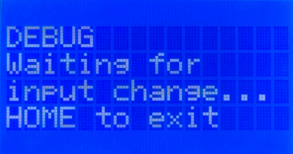
MASTERCELL NGX inSIGHT screen in Messaging Mode showing DEBUG and Waiting for input change

The MASTERCELL NGX in Messaging Mode, waiting for an input to change. Press HOME to exit.

The MASTERCELL NGX stays in Messaging Mode until you press the HOME button, which takes you back to the main menu. While the MASTERCELL NGX is in Messaging Mode, the backlight stays on. This is different from normal operation, where the screen and the backlight both turn off to minimize battery draw. If the backlight is on, you know the MASTERCELL NGX is still in Messaging Mode.

Watching a Single-Case Input

Let’s start with a simple input. On a standard system, your horn is input 9. Always check the configuration sheet that came with your kit to confirm the input and output numbers for your build, because your configuration sheet is the single point of truth for input numbers, output numbers and wire colors.

With the MASTERCELL NGX in Messaging Mode, press the horn button. The screen shows you what the MASTERCELL NGX saw and what it did in response.
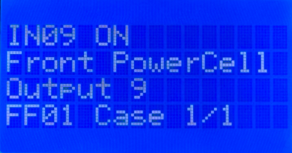
MASTERCELL NGX inSIGHT screen in Messaging Mode showing input 9 on commanding output 9 on the Front POWERCELL

Turning the horn on. Messaging Mode shows input 9 commanding output 9 on the Front POWERCELL.

Reading this screen from the top: the first line, IN09 ON, tells you the MASTERCELL NGX saw input 9 turn on. The second line, Front PowerCell, tells you which cell it is commanding. The third line, Output 9, tells you which output on that cell. The fourth line, FF01 Case 1/1, tells you two things. FF01 is the internal address we use for the Front POWERCELL. Case 1/1 tells you this is case 1 of 1, meaning this input has a single case assigned to its ON state.

Now release the horn button. The screen updates to confirm the input turned off.
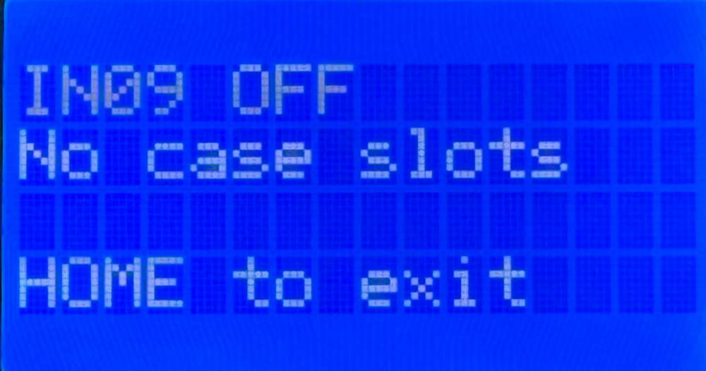
MASTERCELL NGX inSIGHT screen in Messaging Mode showing input 9 off with no case slots

Releasing the horn. Messaging Mode confirms input 9 turned off. The horn input has no OFF case slots.

The first line, IN09 OFF, confirms the MASTERCELL NGX saw input 9 turn off. This is useful on its own, because it confirms the switch released cleanly and is not hung on. The second line reads No case slots. This tells you the horn input has no case slots available for its OFF state. There is nothing for the MASTERCELL NGX to command when the horn turns off, which is exactly how the horn is designed to work.

Watching a Multi-Case Input

Now let’s look at a more involved input. On a standard system, your ignition is input 1. Again, confirm this against your own configuration sheet.

With the MASTERCELL NGX in Messaging Mode, turn the ignition on. The screen shows the first case.
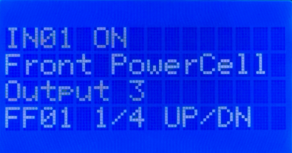
MASTERCELL NGX inSIGHT screen in Messaging Mode showing input 1 on commanding output 3 on the Front POWERCELL, case 1 of 4

Turning the ignition on. Messaging Mode shows the first of four ON cases, with UP and DN to scroll through the rest.

This screen reads much like the horn did. Input 1 turned on, and the MASTERCELL NGX is commanding output 3 on the Front POWERCELL. The difference is on the fourth line. FF01 1/4 tells you this is case 1 of 4, so this input has four cases assigned to its ON state. The UP/DN prompt tells you to use the SCROLL UP and SCROLL DOWN buttons to step through the rest of the cases. This prompt takes the place of the HOME to exit line, but the HOME button still exits Messaging Mode.

Scroll down to see the next case.
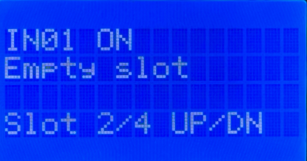
MASTERCELL NGX inSIGHT screen in Messaging Mode showing input 1 on with an empty case slot, slot 2 of 4

The second slot for the ignition input is empty. Available slots that are not programmed show Empty slot.

This screen shows an empty slot. The default ignition configuration uses only the first ON case, but there are four slots available. The second line reads Empty slot, meaning this slot is available but has nothing assigned to it. Notice the fourth line reads Slot 2/4 instead of leading with an address like FF01. That is because an empty slot has no cell or output assigned to it, so there is no internal address to display.

This is worth pausing on, because it is a different situation from the horn. When the horn turned off, the screen read No case slots, meaning no slots exist for that state at all. Here the screen reads Empty slot, meaning the slot exists and is available, it just has not been programmed. You would keep scrolling to view the remaining slots for this input.

When you turn the ignition off, Messaging Mode confirms the input turned off and shows you the cases assigned to its OFF state.
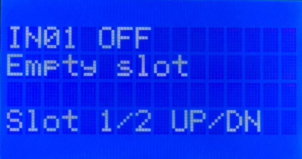
MASTERCELL NGX inSIGHT screen in Messaging Mode showing input 1 off with two available OFF cases

Turning the ignition off. Messaging Mode confirms input 1 turned off and shows two OFF cases to scroll through.

The first line confirms input 1 turned off. The fourth line shows this input has two cases available for its OFF state, with the UP/DN prompt to scroll through them. OFF cases are what let your system do something when a switch turns off, such as running a cooling fan for a set period of time after you shut off the ignition.

What This Tells You

Messaging Mode is one of the most powerful troubleshooting tools in your Infinitybox system because it confirms the whole chain from your switch to your output. Say your horn is not working. Put the MASTERCELL NGX into Messaging Mode and press the horn button. Watching the screen tells you three things at once.

First, it confirms your switch is working. If IN09 ON appears when you press the button, the switch is doing its job and the MASTERCELL NGX is seeing it. If nothing appears, the problem is upstream at the switch or its wiring, not in the rest of the system.

Second, it confirms you have the correct MASTERCELL NGX input wire connected to your switch. If you press the horn button and the screen shows a different input number, you know the wrong input wire is landed on that switch, and you can correct it.

Third, it confirms the correct cell and output are being commanded. The screen shows you exactly which POWERCELL and which output the MASTERCELL NGX is telling to turn on, so you can confirm the command is going where you expect and check your configuration sheet against what you see.

Working through your car this way takes the guesswork out of troubleshooting. Instead of chasing a problem blind, you can watch the MASTERCELL NGX see your switch and command your output, and pinpoint exactly where the chain breaks down.

You can download the entire MASTERCELL NGX inSIGHT document by clicking this link.  This includes all the features and functions.

Questions?

Messaging Mode gives you a real-time window into how your MASTERCELL NGX responds to every switch in your car. It is one more diagnostic tool built into the inSIGHT screen to help you wire and troubleshoot with confidence. If you have any questions about Messaging Mode or any other part of your Infinitybox system, contact our technical support team through our contact form or give us a call at (847) 232-1991.
Polling Your Cells with the MASTERCELL NGX

The System Inventory screen on your MASTERCELL NGX shows you a list of every device connected on your Infinitybox network. Once you know a device is there, you can dig deeper into it to see how it is working. We call this polling. When you poll a cell, the MASTERCELL NGX shows you real-time information about that device right on the inSIGHT screen. This blog post is part of our series on the diagnostic functions built into the inSIGHT screen. We introduced the inventory list in our post on the MASTERCELL NGX System Inventory screen. In this post, we take the next step and poll the cells in that inventory.

The MASTERCELL NGX brings this powerful diagnostic capability to the Next Generation IPM1 Kit and puts it on the inSIGHT screen where it is easy to reach.  There is much more information given on our Next Generation System than on our Legacy System.

Please note that this blog post covers the MASTERCELL NGX in our Next Generation IPM1 Kit. These inSIGHT diagnostic tools are specific to our Next Generation hardware. If you have our Legacy 3-Cell Kit or 20-Circuit Kit, search through our blog archives for the diagnostic tools that came with those systems.

How to Poll a Cell

Start at the System Inventory screen. Press the HOME button on your MASTERCELL NGX to bring up the main menu, use the SCROLL UP and SCROLL DOWN buttons to move the cursor to System Inv and press SELECT. This brings up the list of every device on your network.

Use the SCROLL UP and SCROLL DOWN buttons to move the cursor to the device you want to poll, then press SELECT. The MASTERCELL NGX drills into that device and shows you its details. What you see next depends on the type of device you selected. We will walk through each one below.

Polling a POWERCELL

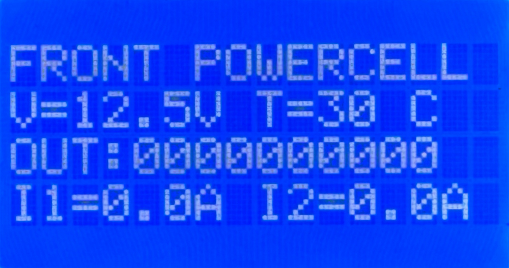
When you poll a POWERCELL, the first line of the screen tells you which POWERCELL you are looking at, such as FRONT POWERCELL or REAR POWERCELL. This confirms you are polling the cell you intended to.

The next line shows two values. The first is the battery voltage measured locally at the POWERCELL, shown as V=12.5V. This is the voltage right at the cell, which is useful for confirming the POWERCELL is getting good power. The second value is the temperature of the POWERCELL in degrees Celsius, shown as T=30 C.

MASTERCELL NGX inSIGHT screen polling the Front POWERCELL showing voltage, temperature, output states and current for outputs 1 and 2

Polling the Front POWERCELL. The first screen shows battery voltage, cell temperature, the state of all 10 outputs and the current for outputs 1 and 2.

The next line shows the state of all 10 outputs on the POWERCELL. There are 10 digits on this line. Reading from left to right, they correspond to outputs 1 through 10. If a digit is a zero, that output is off. If it is a one, that output is on. This lets you see at a glance which outputs the POWERCELL is commanding on and which are off.

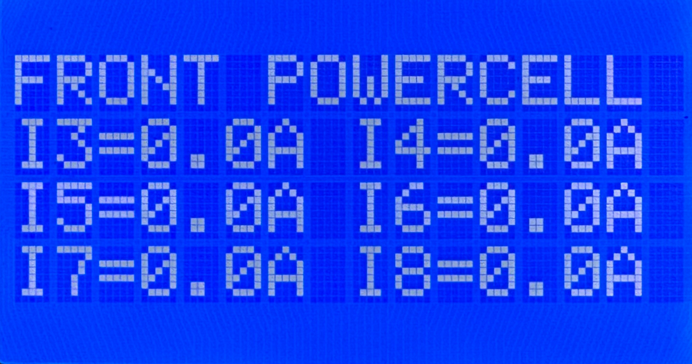
Below the output states, the screen shows the current draw for each output. Each value is displayed as IX=Y.YA, where X is the output number and Y.Y is the current flowing through that output in amps. These current values update in real time. The first POWERCELL screen shows the current for outputs 1 and 2.

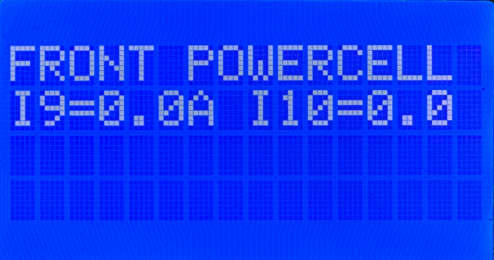
Because a POWERCELL has 10 outputs, the current values run across three screens. Use the SCROLL UP and SCROLL DOWN buttons to move through them. The first screen shows the current for outputs 1 and 2. The second screen shows outputs 3 through 8. The third screen shows outputs 9 and 10.

MASTERCELL NGX inSIGHT screen polling the Front POWERCELL showing real-time current for outputs 3 through 8

The second POWERCELL poll screen shows the real-time current draw for outputs 3 through 8.

MASTERCELL NGX inSIGHT screen polling the Front POWERCELL showing real-time current for outputs 9 and 10

The third POWERCELL poll screen shows the real-time current draw for outputs 9 and 10.

Using the POWERCELL Poll to Troubleshoot

The real power of polling a POWERCELL comes from reading the output states and the current draw together. The output state tells you what the POWERCELL is commanding. The current draw tells you what is actually happening on the wire. When those two disagree, you have found a problem.

Here is the case to watch for. You command an output on and its digit on the output line reads one, but the current for that output reads 0.0A. The POWERCELL is doing its job and switching the output on, but no current is flowing. That points you to a break somewhere in that circuit. The most common causes are a blown fuse, a broken wire, a bad ground or a burned-out bulb. Any one of these breaks the path that current needs to flow through, so the output turns on but nothing draws power.

The healthy case is just as useful. When you command an output on and the current reading matches the load you expect for that circuit, you have confirmed the whole circuit is good from the POWERCELL all the way through to the load and back to ground. Being able to see that real current in real time takes the guesswork out of troubleshooting and points you straight at the circuit that needs attention.

Polling an inMOTION Cell

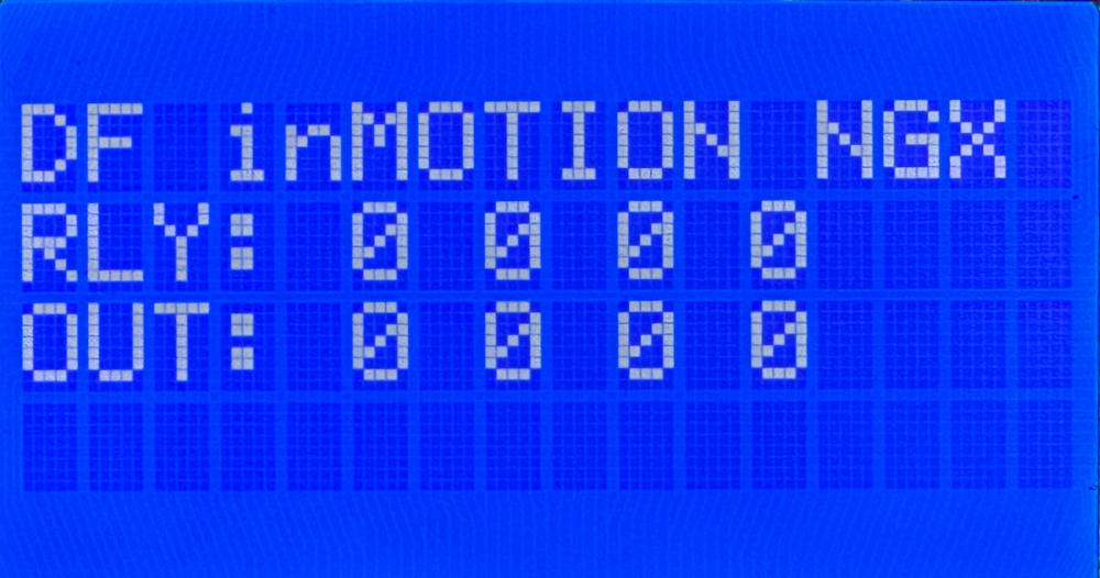
When you poll an inMOTION Cell, the first line of the screen tells you which inMOTION Cell you are looking at. The MASTERCELL NGX identifies it by its door position, such as DF for Driver Front, PF for Passenger Front, DR for Driver Rear or PR for Passenger Rear.

MASTERCELL NGX inSIGHT screen polling the Driver Front inMOTION Cell showing the state of the relay and MOSFET outputs

Polling the Driver Front inMOTION Cell. The RLY line shows the state of the four relay outputs and the OUT line shows the state of the four MOSFET outputs.

The inMOTION Cell has two rows of output states. The RLY line shows the state of the four relay outputs. These come from the two H-bridge relays inside the inMOTION Cell that drive functions like your power windows and power door locks. The OUT line shows the state of the four MOSFET outputs. As with the POWERCELL, a zero means that output is off and a one means it is on.

To see how the outputs on your inMOTION Cell are mapped to the functions in your car, check the configuration sheet that came with your IPM1 Kit. Your configuration sheet is the single point of truth for how each output is assigned in your system.

Polling inVIEW and inCONTROL

Your inVIEW and inCONTROL peripherals will appear in the System Inventory list along with your POWERCELLs and inMOTION Cells. This confirms that they are connected and communicating on your network. In the current version of our software, polling an inVIEW or an inCONTROL does not display any information. They show up in inventory, but there is no detail screen to drill into.

You can download the entire MASTERCELL NGX inSIGHT document by clicking this link.  This includes all the features and functions.

Questions?

Polling your cells from the MASTERCELL NGX gives you a clear, real-time view of what every device on your network is doing. It is one more diagnostic tool built into the inSIGHT screen to help you wire and troubleshoot your car with confidence. If you have any questions about polling your cells or any other part of your Infinitybox system, contact our technical support team through our contact form or give us a call at (847) 232-1991.

MASTERCELL Input Troubleshooting and Diagnostics

Our Infinitybox system has powerful diagnostic and troubleshooting features built into it.  The MASTERCELL in your 20-Circuit Kit includes our inSIGHT LCD Screen.  This screen is your window into the Infinitybox system and it gives you access to the MASTERCELL Input Troubleshooting and Diagnostics.  By pressing a few buttons on the MASTERCELL, you can put it into its Messaging Mode.  This blog post and the attached video will show you how the Messaging Mode can help you wire your car faster and identify problems easily.

All of your switches connect to the MASTERCELL.  These include your ignition and starter switches, your turn signal switches, your brake pedal switch, the switches for your lighting, your fuel pump and cooling fan triggers and any other switches that you have for your accessories.  The MASTERCELL continuously watches the state of your switches.  If it sees one of these inputs turn on or off, it sends commands to the POWERCELLs or inMOTION cells in your system and commands them to turn an output on or off.

The MASTERCELL can be put into its Messaging Mode.  This mode opens up the MASTERCELL Input Troubleshooting and Diagnostics feature in your Infinitybox 20-Circuit Kit.  To put the MASTERCELL into Messaging Mode, you simply press and hold the “SCROLL UP” and “SELECT” buttons under the clear cover.  These are the two buttons on the right, under the inSIGHT LCD screen.  Press these buttons together, hold them for one second then let them go.  You will get a message on the screen that says “inSIGHT WILL DISPLAY ALL INPUT CHANGES FROM ANY SOURCE”.  You will also note that the back light of the inSIGHT LCD will turn on and stay on.

When you turn any MASTERCELL on or off, the inSIGHT screen will confirm that.  It will tell you which input the MASTERCELL say turn on or off.  It will also tell you which cell it is supposed to be controlling and which output.

The following video goes through this in detail.  You can see which buttons to press to put the MASTERCELL into Messaging Mode.  You will also see what the messages on the MASTERCELL screen look like when you turn inputs on and off.  Check out the video here.

Messaging Mode is a very powerful tool.  You can use it as you go through the process of wiring your car or truck with our Infinitybox system.  You can wire each switch, step by step, then use Messaging Mode to confirm that you have the correct input wired to the switch by following the details of your Configuration Sheet.  You can also use this to confirm that you switch is working correctly and that you have good grounds for each of your switches.

If you have problems on the road, you can easily put the MASTERCELL into its Messaging Mode and check for any issues with your switches or the wiring from the MASTERCELL.  No tools are needed.

If you have any additional questions about the MASTERCELL Input Troubleshooting and Diagnostics features of the Infinitybox system, click here to contact our team.

MASTERCELL Polling Video

We pack a ton of powerful diagnostic tools into our Infinitybox 20-Circuit Kit.  With no tools, you can use the inSIGHT screen on the MASTERCELL to learn about everything that is going on in your car’s electrical system.  There is no other wiring harness on the market that can get you that power.

We just published another video going through the specifics of the built-in troubleshooting and diagnostic tools in your Infinitybox system.  This new video covers Polling the system from the MASTERCELL.  When the MASTERCELL power up, it takes an inventory of all of the cells on the CAN network.  This includes your POWERCELLs, inMOTION Cells, inVIRONMENT cells and inTOUCH NET.  From the MASTERCELL screen, you can easily check to make sure that all of the cells are properly communicating on the CAN network.

You can also dig deeper into each cell by polling it from the MASTERCELL screen.  By polling the POWERCELLs, you can get a measurement of the battery voltage measured locally at the POWERCELL.  You can also get a reading of the temperature of the POWERCELL.  You also get a measurement of the Charge Pump voltage on the POWERCELL.  This is a safety system that we monitor to make sure that the POWERCELL is operating correctly.  Lastly, you can get a picture of which outputs are on and off on the POWERCELL.

If you poll the MASTERCELL, you can get a real-time status of all of the switches that are connected.  This is really helpful for troubleshooting and checking your switches as you wire them to the Infinitybox system.

You can watch the new video that goes through polling the system from the MASTERCELL in detail.

You can download our full Diagnostic and Troubleshooting Guide for the 20-Circuit Kit by clicking this link.

You can click on this link if you have any additional technical questions about wiring your car or truck with our Infinitybox system.  

Download the New Diagnostic & Troubleshooting Document

One of the most powerful features of our Infinitybox system is the diagnostic and troubleshooting capabilities that it has.  You can point to exactly where problems are in your electrical system with a few presses of buttons on your MASTERCELL and a glance at the LED indicators on the POWERCELL.  No scanners, tools or laptops are necessary.  We just published a new diagnostic and troubleshooting document in the Resources section of our website.

This new diagnostic and troubleshooting document covers all these built-in tools.  Each is shown with pictures and examples to show you what to look for on your MASTERCELL inSIGHT screen and the POWERCELL output indicator lights.

This new diagnostic and troubleshooting document shows covers these topics:

  1. The basics of Infinitybox diagnostics
  2. How to check the CAN cables
  3. How to check your switches
  4. How to check your outputs
  5. How to read the built-in Error Log
  6. How to use the POWERCELL over ride headers

You can get to this new Diagnostics and Troubleshooting guider under “Installation Instruction & Documentation” in the Reference section of our website.  You can also download the document by clicking this link.

Our technical support team is always available via email or the phone to walk you through getting your car wired with our Infinitybox system.  Click on this link to contact us for support or with questions.

Error Log

There are lots of things that set our Infinitybox wiring system apart from traditional harnesses.  Our troubleshooting and diagnostics is probably one of the most significant features that we offer.  The system will tell you where there are problems in the wiring harness, with no tools required.

One of the more significant features that is built into every one of our systems is our Error Log.  This is an advanced troubleshooting tool that can help to identify problems with a system installed in any vehicle.  The system actively monitors key parameters in the wiring harness.  If these go out of their expected range, the MASTERCELL stores these errors and has the capability to display them back for problem solving.

Let’s start with a deeper dive into how the system works.  When you turn on a switch, the MASTERCELL sees the input get grounded.  It sends a signal to the POWERCELL to turn on an output.  Before the POWERCELL can turn on that output, it needs to check to make sure that everything is safe to do so.  There are three critical parameters that the POWERCELLs check before they can turn on an output: the primary battery voltage, the charge pump voltage and the POWERCELL temperature.  The POWERCELL is continuously monitoring these values and making decision on what to do with them.

The primary battery voltage is an easy one.  The voltage that the POWERCELL is fed from the battery has to be in a specific range.  A charged battery should be at about 12.8 volts.  When the engine is running and the alternator is charging, that voltage should be between 13.8 to 14.2 volts.  The Infinitybox system has internal high and low limits that it watches for the primary battery voltage.  The system can operate down to 6.5 volts and up to 19.0 volts.  If the measured voltage goes outside of these limits, the POWERCELL will shut the outputs off for safety.  In general, your system should be operating between 12.2 and 14.2 volts.  If you’re outside of that, you have a battery or charging issue.

The next one is charge pump voltage.  This is an internal measurement that we take to assess the health of the POWERCELL.  A charge pump is exactly what it sounds like.  We have circuitry on the board that pumps up a charge and stores it.  This stored charge is used to turn the MOSFETs on.  We don’t use relays on the POWERCELL, we use solid-state MOSFETs.  These can do a lot more than a relay but they need to be turned on a specific way.  That’s what the charge pump does.  We monitor the charge pump voltage and display it as part of the POWERCELL statistics.  Depending on the software version, some systems will display CP Volts.  Other systems may display CP Delta.  If  your system shows CP volts, this number should be above 22-volts.  If your system shows CP Delta, it should be above 12.0.  Again, this in an internal measurement that we use to assess the health of the POWERCELL.

The last measurement that we take is board temperature.  Each board has a small temperature sensor mounted on it.  This lets the processor monitor the temperature on the printed circuit board.  This temperature is a combination of the heat generated on the board and the heat from the environment that the POWERCELL is mounted in.  All of the components on the POWERCELL boards are rated to 125 degrees Celsius (257 degrees Fahrenheit).  If the board temperature measured by the processor approaches this 125 C limit, it shuts the outputs down for safety.

So lets look at the error log.  If a POWERCELL records an error, it sends it to the MASTERCELL which stores it in a list.  The MASTERCELL stores 8 errors.  New errors that are recorded push the oldest errors out of this list.  The MASTERCELL reports the Uptime when the error was recorded, the cell that reported it and the outputs associated with it.  The uptime is a clock that starts when the system is powered up.  You can see this when it is running normally.  This is not a real-time clock because it does not continue to run when the system is shut down.

To get to the error log, you first remove the clear cover from the MASTERCELL.  Then you press and release the HOME and SCROLL DOWN buttons under the screen.  Hold them together for one second then let them go.  The MASTERCELL will display any errors that it has stored.  If you want to stop the error log process at any time, simply press and hold the HOME button for 5 seconds.

Our technical support team can learn a lot about your electrical system by looking at the events recorded in the error log.  It is usually easiest for you just to record a video of the error log running with your smart phone and send that to our team.  We can analyze it for you.

By looking at the events in the error log, we can identify problems with your grounds, your battery, your charging system and how you have the system installed in your car.  Check out this video to learn more.


Contact our technical support team if you have any questions about our error log, our diagnostics, our troubleshooting capabilities or any other questions related to our Infinitybox wiring system.

Output Voltage

We get a lot of questions about how the POWERCELL outputs work on our Infinitybox systems.  Here are answers to the two most common questions.

First, a lot of customers ask if we do anything to modify the voltage on the outputs on the POWERCELL when they are on.  The answer is that we do nothing.  The POWERCELL is going to put out whatever voltage it gets in from the battery.  If the battery is low, the POWERCELL is going to output the same low output voltage.  If the alternator is charging, the POWERCELL is going to output the same voltage as the battery is seeing.

The second question that we get from customers is why there is voltage on the POWERCELL output pins when the output is off.  This voltage is part of our diagnostics on the POWERCELL.  When you wire your car with Infinitybox, we give you powerful diagnostic capabilities that you can’t get from a traditional wiring harness.  For our output detection circuit, there is a small amount of current that leaks out of the POWERCELL output.  This is less than 100 micro-amps.  If you have everything connected properly, this leakage current flows through the fuse, through he output connector, through the wire, through the load (light, fan, ECU, etc.) to ground.  If there is a break anywhere in this chain, this leakage current flows back into the LED on the POWERCELL output, causing it to glow dimly.  This is your indicator to check the fuse, look for a break in your harness, check your ground or check for a problem in your load like a burned out light bulb.

If you were to measure the open circuit voltage on a POWERCELL output with a multimeter, you would measure about 2.8-volts.  This is absolutely normal.  Click on this link to download our diagnostics manual to learn more about this.  

If you have any questions about this post or anything else related to wiring your car with our Infinitybox system, give our tech team a call at (847) 232-1991.