 Copyright 2026 Infinitybox, LLC. All Rights Reserved.
 Polling Your Cells with the MASTERCELL NGX
The System Inventory screen on your MASTERCELL NGX shows you a list of every device connected on your Infinitybox network. Once you know a device is there, you can dig deeper into it to see how it is working. We call this polling. When you poll a cell, the MASTERCELL NGX shows you real-time information about that device right on the inSIGHT screen. This blog post is part of our series on the diagnostic functions built into the inSIGHT screen. We introduced the inventory list in our post on the MASTERCELL NGX System Inventory screen. In this post, we take the next step and poll the cells in that inventory.
The MASTERCELL NGX brings this powerful diagnostic capability to the Next Generation IPM1 Kit and puts it on the inSIGHT screen where it is easy to reach. There is much more information given on our Next Generation System than on our Legacy System.
Please note that this blog post covers the MASTERCELL NGX in our Next Generation IPM1 Kit. These inSIGHT diagnostic tools are specific to our Next Generation hardware. If you have our Legacy 3-Cell Kit or 20-Circuit Kit, search through our blog archives for the diagnostic tools that came with those systems.
How to Poll a Cell
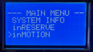
Start at the System Inventory screen. Press the HOME button on your MASTERCELL NGX to bring up the main menu, use the SCROLL UP and SCROLL DOWN buttons to move the cursor to System Inv and press SELECT. This brings up the list of every device on your network.
Use the SCROLL UP and SCROLL DOWN buttons to move the cursor to the device you want to poll, then press SELECT. The MASTERCELL NGX drills into that device and shows you its details. What you see next depends on the type of device you selected. We will walk through each one below.
Polling a POWERCELL
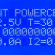
When you poll a POWERCELL, the first line of the screen tells you which POWERCELL you are looking at, such as FRONT POWERCELL or REAR POWERCELL. This confirms you are polling the cell you intended to.
The next line shows two values. The first is the battery voltage measured locally at the POWERCELL, shown as V=12.5V. This is the voltage right at the cell, which is useful for confirming the POWERCELL is getting good power. The second value is the temperature of the POWERCELL in degrees Celsius, shown as T=30 C.
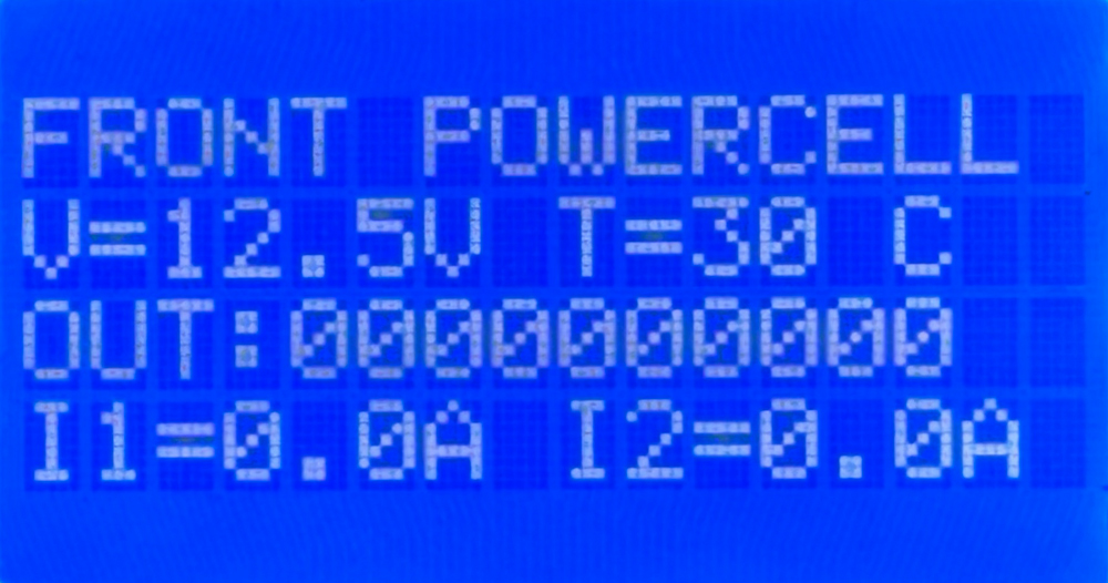
Polling the Front POWERCELL. The first screen shows battery voltage, cell temperature, the state of all 10 outputs and the current for outputs 1 and 2.
The next line shows the state of all 10 outputs on the POWERCELL. There are 10 digits on this line. Reading from left to right, they correspond to outputs 1 through 10. If a digit is a zero, that output is off. If it is a one, that output is on. This lets you see at a glance which outputs the POWERCELL is commanding on and which are off.
Below the output states, the screen shows the current draw for each output. Each value is displayed as IX=Y.YA, where X is the output number and Y.Y is the current flowing through that output in amps. These current values update in real time. The first POWERCELL screen shows the current for outputs 1 and 2.
Because a POWERCELL has 10 outputs, the current values run across three screens. Use the SCROLL UP and SCROLL DOWN buttons to move through them. The first screen shows the current for outputs 1 and 2. The second screen shows outputs 3 through 8. The third screen shows outputs 9 and 10.
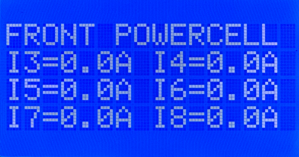
The second POWERCELL poll screen shows the real-time current draw for outputs 3 through 8.
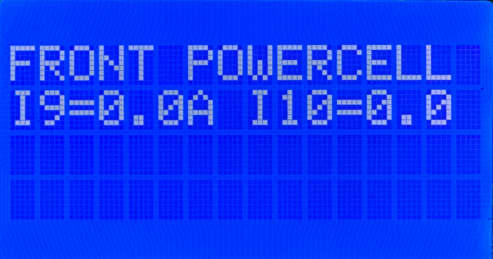
The third POWERCELL poll screen shows the real-time current draw for outputs 9 and 10.
Using the POWERCELL Poll to Troubleshoot
The real power of polling a POWERCELL comes from reading the output states and the current draw together. The output state tells you what the POWERCELL is commanding. The current draw tells you what is actually happening on the wire. When those two disagree, you have found a problem.
Here is the case to watch for. You command an output on and its digit on the output line reads one, but the current for that output reads 0.0A. The POWERCELL is doing its job and switching the output on, but no current is flowing. That points you to a break somewhere in that circuit. The most common causes are a blown fuse, a broken wire, a bad ground or a burned-out bulb. Any one of these breaks the path that current needs to flow through, so the output turns on but nothing draws power.
The healthy case is just as useful. When you command an output on and the current reading matches the load you expect for that circuit, you have confirmed the whole circuit is good from the POWERCELL all the way through to the load and back to ground. Being able to see that real current in real time takes the guesswork out of troubleshooting and points you straight at the circuit that needs attention.
Polling an inMOTION Cell
When you poll an inMOTION Cell, the first line of the screen tells you which inMOTION Cell you are looking at. The MASTERCELL NGX identifies it by its door position, such as DF for Driver Front, PF for Passenger Front, DR for Driver Rear or PR for Passenger Rear.
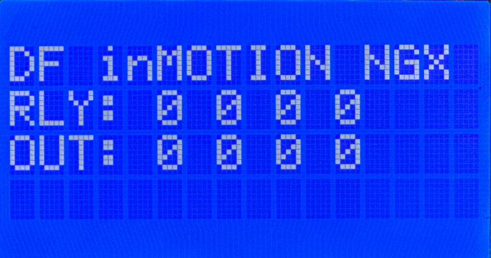
Polling the Driver Front inMOTION Cell. The RLY line shows the state of the four relay outputs and the OUT line shows the state of the four MOSFET outputs.
The inMOTION Cell has two rows of output states. The RLY line shows the state of the four relay outputs. These come from the two H-bridge relays inside the inMOTION Cell that drive functions like your power windows and power door locks. The OUT line shows the state of the four MOSFET outputs. As with the POWERCELL, a zero means that output is off and a one means it is on.
To see how the outputs on your inMOTION Cell are mapped to the functions in your car, check the configuration sheet that came with your IPM1 Kit. Your configuration sheet is the single point of truth for how each output is assigned in your system.
Polling inVIEW and inCONTROL
Your inVIEW and inCONTROL peripherals will appear in the System Inventory list along with your POWERCELLs and inMOTION Cells. This confirms that they are connected and communicating on your network. In the current version of our software, polling an inVIEW or an inCONTROL does not display any information. They show up in inventory, but there is no detail screen to drill into.
You can download the entire MASTERCELL NGX inSIGHT document by clicking this link. This includes all the features and functions.
Questions?
Polling your cells from the MASTERCELL NGX gives you a clear, real-time view of what every device on your network is doing. It is one more diagnostic tool built into the inSIGHT screen to help you wire and troubleshoot your car with confidence. If you have any questions about polling your cells or any other part of your Infinitybox system, contact our technical support team through our contact form or give us a call at (847) 232-1991.

 Copyright 2024, Infinitybox, LLC. All Rights Reserved.
  Copyright Infinitybox, LLC 2021. All Rights Reserved.
  Copyright Infinitybox, LLC 2021. All Rights Reserved.
  Copyright Infinitybox, LLC 2021. All Rights Reserved.


 Copyright Infinitybox, LLC 2021. All Rights Reserved.
 Copyright Infinitybox, LLC 2021. All Rights Reserved.
